Ian_C's workbench - P4 and S7 allsorts

Injector by silver soldering - new things to learn
  • Ian_C

    Western Thunderer
    Egged on by the estimable Mr McKenzie and the ever present Adrian I've had a go at silver soldering. I already had a tiny butane torch so all I had to acquire was some silver solder, a suitable flux and a little heat resistant block to work on. I went for Easy Flo borax based flux powder and a couple of solders, one 'hard' and the other 'extra easy'. I purchased online from Cooksongold - Jewellery Making Supplies | UK Supplier , but there are plenty of other places. The difference between hardness and easiness being the melting point of the solder. My hard solder melts in the range 745 - 778 C and the easy 630 - 660 C. The latter is similar to Brian's Easy-flo 1 recommendation I think.

    The soft soldered injector was taken apart and all the solder cleaned off. A few parts had to be re-made to obtain a proper interference fit. The wires were soldered into the main body using the hard solder and the other parts were added using the lower melting point solder.

    First attempt at silver soldering, so what did I learn?
    1. There are a lot of really irritating people on You Tube who can spend a long time conveying no useful information on silver soldering. I guess I knew that anyway.
    2. Unlike soft soldering it's not so easy to prod things into alignment when the solder is fluid. You really do need to get everything in position before soldering and be sure that it'll stay there when heated.
    3. Applying the right amount solder to each joint is difficult (for me at this stage). The flux spits and bubbles when heated so resting a small piece of solder on the joint before heating doesn't work as the flux pops it off. I ended up fluxing, heating to dry and melt the flux, flame away, solder placed on joint, heat again until the solder flows. Which practically means that the item has to be assembled one joint at a time.
    4. Given that most silversmithing work is on a comparable scale to this model making work it's a mystery to me why the solder is supplied in such a large format. As Brian suggested, I ended up hammering the solder down to a thin strip and cutting off tiny bits with the snips. Blimey it's hard stuff though, and hammering seems to work harden it. Per Brian's suggestion, I haven't come across any solder in foil form yet, although I have seen solder paste.
    5. I agree with Adrian that the lower temperature solder flows more readily than the higher. But they all flow very nicely and it is gratifying to see the solder flash shiny and flow into the joint.
    6. Unlike a soldering iron you have to control the temperature of the work with the flame and how it's applied. It's another variable to get my head around and you have to watch the work closely.
    7. It gets easier with practice. Needless to say I didn't practice before jumping straight in, although adding the last parts to the injector was quicker, easier and neater than adding the first parts. It shows!
    Here it is...
    injector silver solder 3.jpg
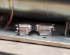
    It's a horrible enlargement of a small part. It ended up much the same as the soft soldered version but as Adrian pointed out I can soft solder the pipework to it now without it coming apart, effectively the same as a brass casting.

    Silver soldering bonus - with this new capability I've been able to make a tiny bit of silver jewellery (is it jewellery when there are no jewels involved?) to add to my partner's charm bracelet. Valentine's Day coming up etc. Presumably all will now be forgiven?
     
    More pipe fittings, a bit more silver soldering and grinding small lathe tools
  • Ian_C

    Western Thunderer
    Thanks for the guidance gents, I think I'm a convert now!

    Here's another small plumbing fitting that's not supplied as a casting. It looks like a water trap or grease separator that's located in the vacuum pipework beneath the LH side of the cab. Same area as the live steam injector. Not very visible, but from some angles you see bits of it, particularly the odd triangular pipe flanges. Why on earth was it designed with triangular flanges when most everything else was round? Reminds me of Toblerone chunks. And Toblerone was 'invented' in 1908 so it's possible that some was being passed around the Derby or Crewe drawing office when the Assistant Senior Flange Draughtsman was looking for inspiration. Maybe.

    Here are the two parts. Lathe and mill job. Drill a hole through a piece of brass rod. Mill it to the triangular section. In the lathe to turn it down and part off to length. Saves having to make two identical triangular flanges and solder them onto a tiny length of rod. The other part is a simple turning.
    vacuum separator parts.jpg


    The assembly is held together with a short length of 0.8mm brass wire, much easier than the blasted injector this time! And the silver soldering is coming along too, no cleaning up of the solder on this part. You can see the tiny mistake when turning one of the flanges!
    vacuum separator assy.jpg

    Perversely I'm enjoying the challenge of making these tiny parts. At some point I'll have to get back to assembling a locomotive.

    Slight change of subject - lathe tools. It's always been a difficulty grinding tiny lathe tools by hand for this sort of work. I recently came across a Japanese or Korean chap on YouTube (didn't make a note and can't find the video again - sorry) who uses a Dremel clamped in the tool post of his small lathe to grind some quite remarkable turning tools from old drill bits. Tiny boring bars and micro thread cutting tools and the like. One day I'll acquire or make a tool & cutter grinder, but until then I've copied his good idea.
    Proxxon toolpost grinding 1.jpg
    Proxxon have a tool post clamp for some of their mini drill handpieces. Here it's being used in the quick change tool post with a carborundum slitting disc to finish a tool to size. It's made from 1/8" square HSS tool steel, ground carefully to near shape and size on a bench grinder and finished on the lathe. The relative height of disk and tool, the rotation of the lathe chuck, the topslide angle and the cross slide position can all be adjusted to cut just about any angle. In this picture the width of the tool is being ground down to size (0.70mm) by adjusting the cross slide and moving the carriage back and forth. The set up looks a bit goofy but it works well if the cuts are very light. Some care has to be taken to get the arbor and disk to run approximately true.
    Proxxon toolpost grinding 2.jpg
    This is a very useful tool for lots of the small, square shouldered turned parts like those above. It is parallel, has a clearance angle on both flanks so it'll cut in both directions, has a zero top rake angle and about 5 degrees clearance angle on the nose. It can be used for turning left and right, grooving and also functions as a parting off tool. It works beautifully in free cutting brass. When set up perpendicular to the work and dead on centre most small parts can be turned without needing to change the tool. Needless to say, light cuts are required to avoid tool deflection. It's entirely possible to make smaller tools than this by this method, but I've no idea what the practical limit is. This is a 400mm between centres lathe, and very nicely made, but it starts to feel a bit ham fisted with work this small. Accuracy isn't a problem because the lathe is DRO equipped and I usually just drive it by the DRO numbers, sort of human CNC (HNC?).

    And so to bed...
     
    Injector pipework complete and some brackets for the ejector exhaust pipe
  • Ian_C

    Western Thunderer
    Finally the live steam injector has been fitted and plumbed in and some of the vacuum pipework beneath the cab has been fitted.
    injector pipework complete.jpg

    Working towards getting the ejector fitted to the firebox and boiler now. From the front end of the ejector is the exhaust steam pipe that runs to an elbow on the smokebox. It's a 3-1/2" O.D. pipe which scales to 2.04mm in 7mm scale, so I can use 2mm brass rod for that. Some time ago I bought some 'LMS large ejector pipe supports' castings from Laurie Griffin, his part 15-016. At this point I discover that they're too small to take 2mm rod and they're rather short so probably won't project far enough from the boiler on the 8F. No choice but to make some from scratch then.

    Took a bit of working out how to make them...
    Starting with 1/8" brass rod - face off - over to milling machine to locate and drill cross holes (cautionary note later) - back to lathe and turn OD to 2.7mm - groove to a diameter slightly less then the pipe through hole diameter, 1.9mm (it's that very useful tiny lathe tool again, see earlier post).
    ejector exhst lathe 1.jpg

    Gently profile the outside of the pipe clamps with a file. Hard to get them identical at this size, but there you go...
    ejector exhst lathe 2.jpg


    Drill the inside diameter to separate the clamp rings. Here's where you need to be careful. If you drilled the cross holes deep enough to project into the material that will be drilled out later then it's a dead cert that drills this size will wander off line, I know because I made that mistake first time round :rant:. So the cross holes are centre drilled to mark position and drilled 0.8mm only until the drill cuts full diameter. Drilling out the internal diameter using a succession of sizes 1.0, 1.5, 1.9mm increases the odds of staying on centre. At 1.9mm the drill breaks through into the grooves and the clamp rings are captured on the drill bit. 1.9mm is slightly undersized for the pipe but that gets sorted later.
    ejector exhst lathe 3.jpg

    The mounting pillars are simply turned from brass rod, diameter 1.3mm and 0.8mm. They're made quite a bit longer than I think they need to be. The excess length disappears inside the boiler on assembly. The rings are cleaned up and the cross hole drilled through to an interference fit with the pillars.
    ejector exhst parts.jpg

    From left to right -
    Silver soldered - parts assembled for soldering - the Laurie Griffin castings for comparison. Note on the silver soldering (and once again thanks to Adrian & Brian McK for pointing me in this direction, it's a huge step forward for me on this sort of work) -I've found that a silver solder fluxed paste is ideal for tiny parts Cup Alloys - Low Temp Silver Solder - www.cupalloys.co.uk . Tiny amounts can be placed exactly where needed with a cocktail stick, just heat the parts to complete the job. Also the silver solder joint is much stronger than a soft soldered joint which makes the cleaning up and fettling much less calamity prone.
    ejector exhst compare.jpg

    Parts are cleaned up and the internal diameter opened up gently with a cutting broach until the 2mm rod just slides through.
    ejector exhst brackets complete.jpg

    Still a few more bits & bobs to make before the ejector can be fitted.
     
    Another small part - ejector exhaust elbow
  • Ian_C

    Western Thunderer
    There's a casting for this in the kit, but it's not great. Couldn't resist making a replacement. In real life I think this is an iron casting. Here it's made from a scrap of N/S, a length of copper rod turned down to 2mm diameter and a small brass turning for the pipe coupling. I tried getting brass rod to bend sharply enough to form the elbow, but no luck. With a couple of relieving cuts inside the bend copper can be tortured into shape OK. Silver soldered together, of course! I think I have all the parts I need to fit the ejector now.
    smokebox elbow.jpg
     
    Ejector complete and installed
  • Ian_C

    Western Thunderer
    Finally it all comes together on the loco.
    s c ejector installed 1.jpg

    Naturally I made my life difficult by not thinking far enough ahead. If I'd had any sense I would have added the drain bosses to the smokebox elbow and the ejector exhaust pipe before fitting them to the loco. Just had to do it the hard way. The drain lines were made from 0.4mm brass wire - much cursing.

    s c ejector installed 5.jpg
    Most locos had another flanged joint on the exhaust pipe a little way forward of the drain boss. It's shown on the C32552 pipe & rod arrangement drawing and appears in many photos. Photos show that some locos didn't have the flange. I don't know whether 8142 had it or not. I chose to omit it, the heavy rain beating down while I pondered flange or no flange and contemplated a trip outside to the workshop to turn said flange having no bearing on the decision of course.

    s c ejector installed 3.jpg
    ejector exhaust bracket 1.jpg

    They are small parts and the enlargement is cruel. Looks OK on the loco though. Makes the model a little different from a typical 8F and a bit more of a portrait of 8142.

    What next? Those sandbox fillers still don't look quite right...
     
    Top feed pipe covers
  • Ian_C

    Western Thunderer
    More boiler fittings. This time the sheet metal covers that were fitted over the semi recessed feed pipes running up from beneath the footplate to the top feed. Brass castings are supplied in the kit. They're usable but they're a bit lumpy and would stand well proud of the boiler cladding. They could probably be filed down to provide a finer edge, but I wasn't convinced. After some fuzzy, low wattage thinking and bit of experimentation this is how they were made...
    top feed pipe cover story.jpg

    1 - I thought I'd try and make them from brass sheet. 0.071 mm or 0.095mm shim seemed about right. Thin enough to be easily formable but not too thin to be workable. After scaling from one of the Wild Swan drawings I worked out that I'd need a circular chord groove 0.6mm deep and 1.8mm wide. That's very close to a radius of 1.00mm so the groove was milled in a lump of spare aluminium using a 2.00mm diameter ball end cutter.

    2- A matching roller was turned from a steel bar offcut with a hole through the centre for a sort of rolling pin axle. The roller profile doesn't exactly match the groove as there's a small allowance for the material thickness. It's a bit statistical at this size so toolmaker accuracy isn't needed.

    3 - Here's the set up in the workshop bench vice. A quick trial with a piece of shim showed that if you don't constrain the shim it twists all over the place as it's formed. So....

    4 - The shim blanks were cut large enough to trap one edge between the vice jaws and the tool (RH side in the photo). That holds them still as you make couple of passes with the roller and gives a nice, straight U channel in the shim. I've no idea what state the shim stock is in and I didn't bother trying to anneal it before forming. Worked just fine straight out of the packet.

    5 - Knowing that there would be a bit of trial and error up ahead, and given how easy it was to make the formed blanks, I made about half a dozen of each. After forming there didn't seem to be a noticeable difference between those from 0.071mm and those from 0.095mm. They all got mixed together and I've no idea which thicknesses ended up on the loco.

    6 - Having cut them closer to size with snips they still need reducing to about 3mm width. Attempts to snip or scalpel them to width weren't great, always ended up with some distortion of the edge. The eventual solution was to solder them to a piece of scrap etch that was somewhat thicker (about 0.4mm? but I didn't measure it) .

    7 - One other thing I'd discovered when experimenting with the first rolled blanks and trying make them conform to the boiler was that they have a tendency to kink and flatten, particularly where there's a rivet impression, making it impossible to make a smooth curve. Similar to how a ductile pipe can be filled with Cerrobend to prevent it kinking when bent, I filled the back of the U groove with solder before I fixed it to the etch scrap. That forced the material in the U to stretch when bent rather than kink and flatten.

    8 - Once fixed to a thicker piece of brass it's easy to hold one edge in the vice jaws and file the other edge exactly to the line. Turn it over to do the other side.

    9 - And there you have a length of shim brass with the correct profile and width to make a top feed pipe cover. It's still fixed to the scrap at this point, and still much longer than necessary.

    10 - With the profile still soldered to the scrap it's relatively easy to bend them to match the boiler cladding. Forming them around a pot of Carr's 188 solder paste got them most of the way there quickly, followed by a bit of careful finger and thumbs, being careful not to put in any kinks. I did notice that there are some stretch marks on the outside of the U where the shim material has elongated, I don't think they'll show once painted. The ends of the profile don't bend uniformly, they stay straighter. But that's OK because they can be cut off to leave a section of uniform curvature which is marked and cut (by piercing saw) to match the top feed and hole in the boiler. Make them very slightly shorter than you think because the circumference of the shim is slightly greater than the circumference of the scrap and they'll wrap around a bit further when separated.

    11 - Once cut to length the shim profile and the supporting scrap are easily separated by heating them up and teasing them apart with the tip of a scalpel. Again, be careful not to kink the shim part. Because of all the solder inside the U it's kind of messy, but a fair amount remains in the U and helps to stiffen the shim profile for subsequent work. The excess solder is very gently removed from the shim profile flanges by filing across the back with a round file.

    12 - The covers are fixed to the boiler cladding with small screws. They're noticeable on the prototype and missing from the brass castings. I added a representation of the screw heads by making rivet impressions freehand with the trusty GW rivet press. The inside of the profile was blacked up with marker pen and the screw locations were marked with callipers and scriber. It was really difficult getting the point of the rivet tool right in the middle of a very narrow flange. It was a bit hit and miss and a couple of profiles were ruined that way. Not to worry there were plenty of blanks, and just enough patience! The finished covers were cleaned up and sweated to the boiler to line up with top feed and the previously made holes where the pipe dives beneath the cladding. The pipes, 2" diameter on the prototype, were made from 1.2mm copper wire.

    The finished covers look like sheet metal parts with a very fine edge, and the slight imperfections give them the look of sheet metal parts that have been removed, clattered around the workshop floor, and re-fitted a a few times. Sometimes our models look a bit too tidy - the prototype was often a bit battered in it's later life. They look OK - I think they'll do.
     
    The Silvertown lubricators
  • Ian_C

    Western Thunderer
    There were two Silvertown lubricators on the RH framing of most 8Fs, the exceptions being the LNER built locos which were fitted with Wakefield lubricators. The forward lubricator had 6 outlets each side for cylinder lubrication and the rearmost had 4 outlets each side for axle box lubrication. Brass castings for the appropriate Silvertown lubricators are supplied in the MOK kit. They're not bad castings and with a bit of work they clean up OK. The small pipe unions are represented on the castings but they're very close together and get a little unresolved during the casting process. All overcome with optimism I tried to drill the unions to take 0.3mm wire, but nothing doing. The cast brass is dead hard and the shape and spacing of the cast unions was a bit statistical.

    The unions were filed off the castings and 0.8mm holes were drilled though in their place.
    castings drilled.jpg

    The outside diameter of the unions scaled to about 0.8mm and I intend to use 0.3mm copper wire (from cutting up a short length of electrical flex) for the pipes. Microbore brass tube from Albion alloys was used in two sizes to make new pipe unions. One tube was 0.8mm x 0.4mm, the other 0.5mm x 0.3mm.
    small tubes.jpg


    By drilling out short lengths of the 0.8mm x 0.4mm to a diameter of 0.5mm it was possible to insert a corresponding length of 0.5mm x 0.3mm tube to make a tube effectively 0.8mm x 0.3mm. The tubes were silver soldered together, taking care not to bung up the 0.3mm hole with solder, and trimmed to a length that left enough sticking out of each side of the lubricator casting.
    more tubes.jpg

    Approximate hexagons were filed on each end of the tubes to represent the pipe fittings before they were silver soldered into the castings. A casting is shown here on a ceramic honeycomb plate. The casting is held steady by stainless steel tapered pins dropped into holes in the plate. It's a jewellery making thing that I came across when I was buying silver solder a few posts ago. I find it very useful.
    set up to solder.jpg

    0.3mm wire is passed through the tubes to represent the oil pipes. A couple of tubes needed easing open with a 0.35mm drill before the wire would pass through. I do wonder if using the two tube diameters was worth the trouble, and possibly just the 0.8m x 0.4mm tube would have done the job without the wire looking to wonky. The cast priming handles are a bit chunky and I thinned the ends a little - still too thick, but I didn't fancy making any finer ones from strips of brass. The wire was soldered in with tiny slivers of 145 solder.lubricators and pipes.jpg

    The arrangement of the pipes varies between locos. On some locos the pipes remain at the height of the unions as they turn inboard towards the inside edge of the framing before dropping down to the framing and over the edge between the mainframes. On other locos the pipes drop from the unions down to the framing first before turning inboard. The earlier locos seemed to have all the pipes high initially. Some later locos had all the pipes low. From photos most locos seem to have a mixture of the two styles- the pipes between the two lubricators dropping down first and the pipes on the front of the front lubricator and the rear of the rear lubricator staying high before dropping down. I imagine that it all got a bit mixed up as locos were overhauled and some pipes replaced. The photo of 48142 seems to show the inside pipes low and outsides high, so that's what I've attempted to model. The pipes were arranged and trimmed on the bench before the lubricators were sweated onto the footplate with 145 solder.
    lubricators assembled 2.jpg
    lubricators assembled 1.jpg

    They're not perfect and I've seen them done better in 7mm, but they'll do for me. And in the end this is a 1966 8F (Paint it black , Rolling Stones was in the charts - seems appropriate for an 8F) so there'll be plenty of crud on the framing from spilled oil and sand.
     

    Attachments

    • tubes soldered in.jpg
      tubes soldered in.jpg
      134.7 KB · Views: 6
    Endless boiler - atomiser steam cock cover
  • Ian_C

    Western Thunderer
    Here's another part that really needs something better than the supplied casting. This is the odd shaped cover that is fitted over the atomiser steam supply cock up on the LH side of the smoke box. At first sight you'd think it's a half teardrop, but it's not. It's hard to describe the shape, sort of a truncated cone with tapered tail. The shape and size can be worked out from the supremely useful C32522 Pipe & Rod arrangement drawing in the Wild Swan book. Worth noting that the early straight throat plate boilers had a different cover here, quite a bit longer and a very different in shape. I can't see what they bothered to fit a cover at all. Both ends of the valve are exposed by cutouts in the cover so it's practically offering no protection to the only parts that are likely to need protection. And why streamlined? Obviously improves the airflow in the critical chimney flange area - or something. Here's a way of making one...

    atomiser cover.jpg

    1. Machine a strip of 1/8" brass to the required thickness , 2.46 mm as it happens. Mark out the basic outline, scribing quite deeply because the marks will need to survive some silver soldering.
    2. Partly drill through the blank diameter 2 mm. Saw around the blank leaving plenty of spare material, and silver solder a length of 2mm brass rod in the hole. The rod is a very handy way of holding the part to work on it, and once shortened it's a useful spigot for locating the finished part on the model.
    3. Held in a vice and basic facets filed on.
    4. Filed up to the marked lines to form the basic outline.
    5. Bit of a scruffy photo, but here the chamfer for the truncated cone shape and the tapered tail is marked on, having blacked it all over with marker pen first.
    6. More filing of facets, taking care not to nibble away at the bottom edge. Here's where the black marker helps. If you leave a tiny sliver of black on the lower edge you know that you've not altered the basic shape when you file the chamfer.
    7. The whole lot is blended together. Getting there now.
    8. The tapered tail and the top edges are blended now. For comparison the cast cover is shown alongside. It's much smaller and not close to the correct shape.
    9. Here's a tricky part, making a representation of the cut outs. The 2mm rod is held in a tiny toolmakers vice which is held in a much bigger machine vice. The cutout scales to about 1.3mm wide. The nearest milling cutter I have is 1.5mm diameter so that'll have to do. The milling machine usually carries an ER32 collet chuck, but so I can actually see what I'm doing on this job I'm using an ER11 chuck that runs very true, which is a blessing when using small cutters.
    10. Positioned by eyeball and DRO the first cut out is made to the correct height. Tiny depth of cut, slow feed rate and plenty of patience get the job done.
    11. Now we have a flat surface and the spindle is on centre a 0.9 mm hole can be drilled right through. The cover is turned over, repositioned and the opposite cut out is made the same way.
    12. A small fitting was turned to represent the steam cock, or at least the bits that are visible through the cutouts in the cover. One end is drilled 0.6mm to accept the steam pipe.
    13. To make things more difficult there's a flange on the cover. I wondered whether to attempt the flange, but decided to got for it. the centre of the fitting was marked on the smoke box and drilled 2.0mm. A piece of brass shim was cut and curved to sit neatly on the smoke box. When it all sat down without big gaps the shim and the cover were removed and silver soldered together along with the valve turning.
    14. The excess shim was snipped off and carefully filed to shape around the cover. An attempt was made to represent the fixing screw heads by poking the flange from behind with a scriber. Partially successful. The flange is nicely annealed after silver soldering so it's very easy to put the fitting in place on the smoke box and gently press the flange down with the end of a cocktail stick to make it sit down tight.
    15. The completed cover was sweated to the smokebox with 145 solder and the steam pipe added from 0.6mm wire.
    We're not done with the boiler fittings yet...
     
    Postscript to the atomiser cover!
  • Ian_C

    Western Thunderer
    Having done all that I found another drawing showing the cover in more detail. It shows that my confident assumption about the cut out on the upper edge of the cover is wrong! Where the end of the valve projects through the cover the cutout is simply a round hole. Oh well, it's staying like that. Next time...
     
    Tube cleaning steam cock - and a new toy
  • Ian_C

    Western Thunderer
    At this stage in its career 48142 had had the steam supply for the tube cleaning cock moved high up on the smokebox with the steam cock itself on a small bracket lower down near the front of the smokebox. Parts made from scratch apart from the cock itself, for which there was a useable brass casting, although it needed a bracket making to mount it to the smokebox.
    tube cleaning cock.jpg

    The new toy is a 6 litre ultrasonic cleaning tank. It's large enough to take the whole loco with a bit of room to spare. Previously I've used a budget 2 litre tank and I never could get it all in at once. Hitherto uncleanable parts are now squeaky clean.
    6 litre ultrasonic tank.jpg
     
    AWS parts
  • Ian_C

    Western Thunderer
    Surprisingly I couldn't find many decent brass castings for the BR AWS equipment. Ragstone Models do have a brass casting for the AWS receiver that hangs under the pony truck, and that's pretty good. There are whitemetal castings for the vacuum tanks but they lack detail such as mounting brackets, dished ends, pipe unions etc. Scratch building once again. No drawings to be found so the main dimensions were estimated from photos. Modelled them on CAD and compared until the proportions looked right. Although at this size some compromises have to be made to accommodate convenient material thickness and the fiddliness of manufacture.
    AWS batt box CAD 1.jpg

    Brass and nickel silver scraps, some turning, soldering and cursing. The battery box was difficult to get right and I had to have two goes at it. The main vacuum reservoir sits on two tiny brackets, which were a pain to make. Also worth noting that the pipe from there main reservoir exits form a boss on the back of the tank, not the end as I'd originally assumed. I've no idea how the smaller timing reservoir is attached to the loco, but it's tucked away behind the ejector pipe so not very visible.

    AWS parts made.jpg
    The main reservoir looks a bit fat in this photo. I'll see how it looks on the loco before making a decision.

    Interesting diversion. I was looking for information on turning small parts using a graver steel, watch and clockmaker fashion. One thing leads to another on YouTube and I ended up watching a video by a chap called Roger Smith showing how he designs and makes a watch case. Not really what I was looking for but fascinating nonetheless. That in turn led me to a watchmaker called George Daniels. Both remarkable characters and supreme craftsmen. Regrettably neither of them were railway modellers! One has to wonder what they'd make of a 7mm locomotive. Something to aspire to then... Roger W Smith rwsmithwatches
     
    AWS conduit clips
  • Ian_C

    Western Thunderer
    AWS conduit clips. Tiny things, but very visible on the LH running plate valence and on the RH lower cab valence. No drawings for these but easy enough to estimate the size from photos. My guess is that the conduit was about 1" in diameter and 0.6mm wire is near enough. The clips are not too difficult to make and we need 10 of them. Goes like this...

    AWS clips story.jpg

    1. Brass shim annealed, for reasons that become clear later. No idea how thick, it was in the scraps box and seemed about right.
    2. Shim is cleaned up and tinned lightly.
    3. Strips 1.4mm wide are cut from the shim and flattened.
    4. The strips are folded over a length of 0.6mm brass wire, tinned side inwards...
    5. ...and clamped carefully hard up to the wire in a toolmaker's clamp. Annealing helps to eliminate the springiness of the shim stock and gives a very tight bend without much effort.
    6. You end up with a lot of these.
    7. The tinned surfaces of the clips are soldered together with a zap from the RSU. That stiffens them somewhat.
    8. The screw heads are represented by putting rivets in freehand with the trusty GW rivet press. Well they're very similar if not identical. The screw heads are surprisingly prominent on the prototype and riveting hard through two layers of annealed shim does squish plenty of material into the riveting anvil to form a decent sized impression.
    9. Cut to length with snips and tidied up.
    Started off with plenty to spare. Scrapped a few in the process. Ended up with only 11. Hoping therefore that more than one doesn't go to live on the floor, not much chance of finding that again.
     
    Last edited:
    AWS done and fitted- mostly
  • Ian_C

    Western Thunderer
    With the battery box fitted in front of the cab and the main reservoir positioned on the framing it it was clear that the reservoir was too fat and short when compared with photos. I eventually found a photo taken from almost dead side on from which I could scale it relative to known sizes. If anybody's interested I reckon it works out as 17.9mm long and 7.33mm in diameter. Serves me right for simply taking the dimensions straight from the Ragstone white metal cast reservoir without checking :(.

    AWS installed RH 1.jpg

    The conduit and clips beneath the cab were zapped on by RSU and the vacuum pipe from the main reservoir was made from 0.3mm wire. One thing that becomes apparent is that filling the rear sand box must have been a right pain as it's almost behind the reservoir and the pipe runs right above and behind it.

    AWS installed RH 2.jpg

    The small timing reservoir was soldered in place tucked away behind the ejector vacuum down pipe. Something I'd not thought about prior to tackling the AWS was that there are small pipes from the ejector vacuum pipe and the timing reservoir entering the cab through the cab front sheet. The holes for them were difficult to mark and drill in situ - one to note if I live long enough to do another AWS fitted 8F! Likewise there's a pipe fitting on the ejector vacuum pipe that would have been easier to fit before the ejector assembly was fitted to the loco. On many photos these small pipes were bent around all over the place - none of your 'ship shape and Swindon fashion' here!
    AWS installed LH 1.jpg

    Conduit was run from beneath the LH side of the cab along the valence to forward of the cylinders where it enters a fitting that takes it inside and out of sight. The wiring conduit seems to have been connected to the end fittings, and sections joined end to end on the long run down the LH side, by means of a flexible tube or hose clipped to the conduit. Those hose connections were represented by a short length of 0.8mm microbore brass tube (left over from the Silvertown lubricators - earlier post) drilled out to 0.6mm to accept the conduit wire. Here are the tiny clips doing their job...

    AWS installed LH 2.jpg

    There's a bit more AWS left to do; the receiver on the pony truck and the bash plate fitted to the buffer beam to protect the receiver from swinging coupling links.
     
    AWS receiver mounting
  • Ian_C

    Western Thunderer
    Last chapter on the AWS. Honest. In the gloom under the pony truck there's a bunch of bracketsmithery that holds the AWS receiver 6 inches or so above track level. It's 1960's thing and unsurprisingly drawings for this are not included in the Wild Swan book, so it's another estimate and approximate job. I imagined that photos showing the AWS receiver installation would be hard to find but 30 minutes of browsing 'The Book of the Stanier 8F 2-8-0s - Part one: Pre-War Engines 48000-48125", Irwell Press, ISBN978-911262-15-2 (splendid book if you're a Stanier fanboy or modelling an 8F) has some half decent views.
    ASW rcvr compilation.jpg

    There's enough here to work out roughly how it's done. (Note to self - must add the diagonal stays to the front footsteps - only just noticed them). Measured up the pony truck and modelled the parts in CAD to make sure it all ends up in the right place before cutting metal.
    CAD 1.JPG CAD2.JPG
    The green receiver is the brass casting from Ragstone Models, the rest fabricated from odds'n'sods. Easy enough, and I didn't bother to add much detail because it's not that visible. Silver soldered together so it can be soldered to the pony truck as a sub assembly without it all coming unstuck.

    AWS rcvr sub assy.jpg

    And just to put it in context here it is compared with a glass of beer. Beer helps to put a lot of things in context.
    AWS rcvr sub assy beer.jpg

    Straightforward to fix it in position on the pony truck. The flexible conduit that carries the receiver wiring onto the loco was made by winding some very fine copper wire round a length of 0.5mm brass wire and tinning the lot with 145 degree solder. I used 145 because it's very fluid and doesn't clog up the detail too much. One end soldered into the receiver outlet and the other bent around to join the receiver mounting plate to make it robust. In reality I think the flexible conduit ended up fixed to the back of the bash plate on the buffer beam, clearly not going to work on the model!
    AWS rcvr mounted.jpg

    And here's the finished article in the Colin Gifford style...
    AWS rcvr complete BW.jpg

    Here's something I've never seen discussed - AWS battery maintenance. There was no means of battery charging provided on the locos so logically the batteries would have to be removed and recharged periodically. How long would a set of batteries last? Days? Weeks? There must also have been battery charging and storage facilities at some steam sheds mustn't there? You have to wonder how well looked after this electrical gubbins was on a typical steam shed.
     
    The smokebox and a load of difficult stuff - part 1
  • Ian_C

    Western Thunderer
    One entry on the finishing off list - "speaker mounting and means of removal". I've kicked this one down the road for a long time, now it needs to be tackled.

    The original plan described many WT posts ago was to insert the DCC circuit board and speaker on a subframe through the underside of the firebox and push them forward inside the boiler with the speaker ending up in the smokebox. It became clear that the DCC module wasn't going to fit that way so it's been relocated to the tender (i.e. kicked a bit further down the road) , where there's enough room. On trying to accomplish the same with the speaker it became clear that that wasn't a practical approach either. Since I definitely want the speaker at the noisy end of the locomotive (human hearing is astonishingly accurate at determining the direction of a sound) the only other way to fit and remove the speaker is through the smokebox door. Fortunately I had not fitted the smoke box door at that point. You've no idea how much work this is going to create!

    There's a casting supplied in the kit that represents both the smoke box front ring and the door. Many posts ago I did some work on it to add the smokebox liner rivets. I didn't think too hard about it at the time. Since the smoke box door now needs to be removable the way this casting fits to the front of the smokebox becomes critical. And here's the first problem. On the prototype the smokebox front ring is a steel pressing that sits inside the smokebox wrapper plate and it riveted to it around the outer flange. What you see is the rounded corner of the ring pressing and the edge of the wrapper plate outside it. The plate is 3/8" thick on the prototype, equals 0.22mm on the model. The way the smokebox is made up on the kit presents double thickness at that edge: the base etch plus a half etched overlay. The resulting edge is way too fat and it inevitably shows the imperfect lamination of etch and half etch. Also the smokebox front casting doesn't quite replicate the prototype in the way it fits the smokebox. It doesn't quite slip inside the smokebox wrapper plate and it doesn't quite cover the front edge of it either, it's sort of undecided. There's one more thing that doesn't look quite right, the door seems a bit flat. More GNR Gresley than LMS Stanier. Hmmm...

    For me the smokebox front if the 'face' of the loco (although not in a Rev W. Awdry sort of way, and in passing it has to be noted that although Henry the Green Engine was clearly a black five the Fat Controller never saw fit to acquire an 8F) and it's easy to lose the character of it if something's not quite right. So it'll have to be rebuilt from scratch. Hadn't planned on this and it looks a bit daunting.

    The first job is the thin the smokebox wrapper by carefully (very carefully - one slip and it's a big mess!) undercutting the inside etch with a cutting disc and peeling out that thickness of material. Nerve wracking stuff. smokebox edge thinning.jpg

    After cleaning up the inside diameter can be measured and a smokebox front ring drawn up. I just copied the prototype using drawings in the Wild Swan book. The ring is easily, if rather wastefully, machined from a lump of brass, and the rivet holes drilled diameter 0.5mm on the milling machine.The inside of the ring is chamfered as per the prototype (the pressing was machined here to provide a seat for the door to seal on) so that there will be a small recess visible around the door when it's fitted. It's there on the prototype and almost impossible to replicate on the model unless you make the ring and door as separate parts like this.
    smokebox ring machine 1.jpg

    Back in the lathe to part off and you get one of these...
    smokebox ring machine 2.jpg
    The original casting is on the left. It's a decent casting, shame I can't use it. The MOK smoke box is formed around etched circular formers and as a result it comes out almost perfectly round. The machined ring is a gentle push fit into the wrapper with hardly any gap around the edge. Looks much better and worth the effort.

    Took a bit of thinking to work out how to make a new smokebox door. I measured the casting and compared it with the profile taken from the Wild Swan book. The cast door is definitely too flat. The dome of the door is a spherical surface apart from the flange at the outside edge. I imagine the traditional way of doing this (unless you have a CNC lathe!) is to mount a length of bar in the chuck and go at it watchmaker style with a toolrest and gravers and a profile template. Never tried that approach to turning and I don't have the tools for it. I came up with another approach that guarantees the geometrical accuracy of the profile and relies much less on hand work.

    First step is to draw the door profile in CAD. Then from the top centre of the curve step off parallel lines at 0.1mm intervals. You can use bigger intervals if you want to spend less time doing numbers on the lathe, but you'll have more hand finishing work to do and there's less control over the profile. Divide the door profile into what is effectively a stack of discs each 0.1mm thick and of a known diameter.
    smokebox door CAD.JPG

    That lot is tabulated in a spreadsheet so I don't lose track of things when I'm on the lathe. The lump of brass bar is turned down to the outside diameter of the door and faced off. A diameter 2.5mm hole is drilled through the centre for the dart boss. Then it's the best part of an hour twirling handles with industrial efficiency and trying not to be hypnotised by the DRO numbers - one cut too far and you have to start again.
    smokebox door machine 1.jpg

    You're sort of making a contour map of the door.
    smokebox door machine 2.jpg

    The surface is then taken down with file (yes - file on lathe = heresy) carefully until all the rings have just disappeared. A scrub with wet & dry (more heresy) and a Garryflex block finishes the door profile. It took a while but it was easier than I thought it would be.
    smokebox door machine 3.jpg

    The diameter is reduced behind the depth of the door to be a close fit in the previously made ring, and the whole thing is parted off.
    smokebox door machine 4.jpg

    The handrail knob holes are drilled on the milling machine and a small part is turned to represent the boss for the dart locking handles.
    smokebox door 5.jpg

    There's at least one more episode of this...
     
    Smokebox door hinges - emotionally damaging and now a bit stuck
  • Ian_C

    Western Thunderer
    I wasn't looking forward to making these parts, and they have turned out to be a pain. First attempts unsuccessful.

    I'd originally thought of soldering a length of tube to a strip and working from there. I actually made some parts to try before changing my mind and deciding to make them from solid. I reasoned that you can't actually hold and work on parts this size as individual items so I fixed the blanks to a sacrificial surface and worked from there.

    A couple of brass lumps are cut roughly to size and soldered to another piece of brass that's large enough to hold in a milling vice. I made a first attempt with soft solder but that failed on final machining when the milling cutter started to peel the workpiece off the base. For the second attempt the blanks were fixed with silver solder, and there were no machining problems with that.
    soldered blanks.jpg

    The lumps are machined away to leave the basic shape.
    machined 1.jpg

    Hinge cut outs are roughly machined (they get cleaned up later with an escapement file) and the hinge pin holes drilled through.
    machined 2.jpg

    The hinges are cut from the main base material to make them easier to finish by hand. Some careful filing to add the radii, and the hinge pockets cleaned up. Looking quite good I thought.
    fettled.jpg

    It went horribly wrong at the next stage...
    scorched.jpg

    The heat needed to re-melt the silver solder was sufficient to destroy the hinges. I tried to heat the base lump rather than let the flame contact the hinge itself. Even so. On one of them it seems like the brass has delaminated before the solder melted. I might have been better leaving them on the original base and heating from the rear. That's a few hours work heading for the bin:headbang:.

    I need to find another way of doing this, but I'm not in the right frame of mind to have another go at the moment. Any suggestions?
     
    Reasonably close to a happy ending - and seeing what you're doing!
  • Ian_C

    Western Thunderer
    Not sure where the line is drawn between determination and obsession, but I had to have another go. This time I went back to the plan A : making the hinge up from tube and strip.

    The strips are cut and filed from 0.25mm N/S, and the tubes are small brass turnings 1.28mm OD and drilled through 0.6mm for the hinge pin. Set up carefully and silver soldered with enough solder to form a fillet between tube and strip. The tube was deliberately slightly too long in order to form the fillet right out to the edges of the strip. It gets filed back to the correct length later. Contains adverts - join the Scale 7 Group!
    tube and strip 1.jpg

    The tube length is corrected, the hinge gap is cut out with a piercing saw and cleaned up with a small file. They're not quite as lovely as the machined from solid ones, but they're OK I think.
    tube and strip finished.jpg
    I get to sleep at night now!
    -----------------------------

    Here's something I discovered recently - watchmaker's eyepieces. They're really cheap (less than £3) and available in a variety of magnifications. Bought a few recently; x3, x4 and x10 magnification. I find myself using them quite a bit on small work - to see if I've filed up to a marked line or started a drill on centre etc. They're a bit cheap, they have plastic lenses, like something out of a Christmas cracker but they help you to see what you're doing and that must improve your work. At that price why wouldn't you have a couple on the bench?

    https://www.cooksongold.com/Jewellery-Tools/-Range=Loupes_^_Magnifiers

    eyepieces.jpg
     
    48142 has a face at last
  • Ian_C

    Western Thunderer
    Having made some half decent hinges I'll be damned if I don't make an opening door. So, proper hinge pivots next.

    Starts with some small turned parts. The secret is to drill the cross hole first in the bar stock and then do the turning in the lathe so that it ends up in the right place on the finished part.
    door hinge turnings.jpg

    A bit of hand work next to make them square and round off the top. They're held in a an old Eclipse pin vice which in turn is held in the bench vice. A length of wire through the cross drilling helps align the part with the jaws of the pin vice which can be used as visual guides for filing square.
    door hinge blocks.jpg

    Working hinges without too much effort.
    door hinges work.jpg

    Takes a lot of parts to replace the single casting. That's 12 parts not including the lengths of wire for the rivets. I can see why a decent casting has some appeal in a kit. There's more to this than meets the eye though! The hinge pivot blocks had to be made twice. I miscalculated the hole position first time round and as a result the hinge axis was a bit too far from the smokebox front ring. Might have got away with it but decided not to. I recall bit of Tom Mallard advice from an old MRJ article - in essence 'one way to improve your work is to re-make anything that you're not happy with'. Something like that. Painful at first, but true. Also the handrail knobs supplied with the kit looked a bit lumpy compared with the prototype, and the handrail wire hole was a bit small. Like turnips strung on a washing line. The handrail actually scales to around 0.9mm diameter, bigger than you think. In 4mm the struggle is to make everything fine enough. In 7mm some things are chunkier than you think. Could have been stuck there but fortunately I found some splendid cast handrail knobs in an old MMP kit. (Diverging a bit - I bought a 7mm 9F MMP kit years ago when I really couldn't afford it. I thought about trying 7mm back then but apart from a couple of Slaters coal wagons but I never really got into it. I still have the MMP kit untouched. It's not state of the art now so it'll probably go on Ebay - minus handrail knobs! ) . All put together by a combination of silver soldering followed by soft soldering. Soldering the details to the lump of brass that is the smoke box door was a real trial. Not quite as hard as the firebox backhead - you'd have thought I'd learn from that, but apparently not. The dart handle and door clamping handle were cannibalised from a Laurie Griffin casting.
    smokebox door all parts.jpg

    Eventually it all comes together and 48142 has a face at last. I think it captures the Stanier look quite well. The smokebox front ring isn't yet soldered into the smokebox wrapper yet, just a push fit. That'll happen when I've made up my mind about speaker mounting and fitting the lead weights (earlier post - much earlier!). And the door does open on the hinges. Imagine the scenes when Mr Fireman swings open the door to shovel out the char only to be be confronted by a couple of tonnes of lead and a giant speaker.
    loco has a face.jpg

    Postscript - amazing what you see on a cruel photograph. The RH handrail end (button, stopper, finial - whatever) is slightly fatter than the LH one. Needs filing down a bit. Tomorrow...
     
    Handrails and knobs
  • Ian_C

    Western Thunderer
    Turns out there are three kinds of handrail knob on the 8F (probably different again on the tender). Two short ones on the smokebox door. Eight the same size on boiler and smokebox. Four odd ones on the firebox. None of the remaining cast knobs were long enough for the boiler and smokebox so I looked elsewhere. I ended up buying a few handrail knobs from Slater's and from Eileen's Emporium, both turned from brass. I could get all three sizes from Slater's but only long ones from Eileen's. Dimensions are shown below...
    7mm handrail dimensions table.jpg

    It would be useful to have this information on the respective websites. I'll add the missing dimensions for Eileen's' when they turn up.

    Of the two the Slater's look slightly better. The ball on the end is closer to scale and it does make a difference. Both need easing out with a cutting broach to take a 0.9mm handrail wire. And both look a little chunky in the stem. Slater's long are a close match in length (A) for the boiler and smokebox knobs so they were put in the little Proxxon drill to have the stem and mounting flange (E) slimmed down a bit with a needle file. Easy enough.

    The firebox handrail knobs are a different proposition. They are mounted to the firebox by a triangular flange and three bolts. There are cut outs in the firebox cladding sheets for these but you can see in photos that the flange and bolt heads are slightly proud of the cladding. Use standard knobs and ignore the difference? Or do it the hard way? Here's the hard way...

    Face off a short length of brass rod and set it upright in a toolmakers vice on the milling machine. Find the centre and drill the centre 1.2mm diameter and the triangular bolt hole pattern 0.5mm diameter. Drill down the rod far enough to make four and a spare including the width of the parting off tool. 6mm just about covers it, which requires a bit of patience with the 0.5mm drill. Then back to the lathe to part off a number of discs 0.25mm thick. Each disc has the required hole pattern in it. Remove the parting off nib and carefully file them triangular using the small holes as a guide.
    firebox handrail knobs 1.jpg

    Insert 0.5mm wire and a Slater's medium handrail knob (modified as before) and silver solder them together. You have to take care to line up the triangle with the handrail orientation, and making everything a push fit helps to keep it straight during soldering. I'm now using a silver solder and flux paste for small parts like this. Just the tiniest blob of paste on the end of a cocktail stick is all it needs and they solder beautifully with just a waft of blowtorch.
    firebox handrail knobs 2.jpg

    Snip off the excess wire and clean them up. I have to admit to using my fingernails as a filing guide on this sort of work so my RH index finger nail is interestingly grooved right now!
    firebox handrail knobs 3.jpg

    I'm going to fix the handrail knobs to the body and leave the handrail off for painting and weathering. Particularly weathering, where you can't have convincing streaks down the boiler with a handrail in the way. I'm counting on being able to thread the handrail on at the end and paint it in situ. There's a slight kink in the handrail at the junction of boiler and smokebox (curse Churchward's tapered boilers and smokeboxes !) but I reckon it'll wriggle through as I've not made the handrail knobs too tight a fit on the handrail.
     
    Top