Ian_C's workbench - P4 and S7 allsorts

Completing the chassis - part 3 - sanding gear complete
  • Ian_C

    Western Thunderer
    What's on the workbench ? Glorious clutter as usual. It's been worse. However much space I make I'll always end up working in about a 6 inch square near the edge. Entropy - "lack of order or predictability; gradual decline into disorder."
    workbench may 18.jpg

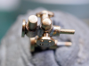
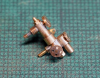
    The sanding gear below the footplate is complete. A satisfying addition of authentic looking gubbins.
    sanding gear 4.jpg
    The sanding nozzles are now the lowest part of the chassis when the wheels are not fitted. Have to take more care when handling the chassis now. The combination of brackets soldered to chassis and 0.9mm brass wire for the sand pipes soldered to the sand boxes makes them reasonably robust. There are no sandbox location hints in the kit so that had to be scaled from drawings in the ever present Wild Swan book.
    sanding gear 5.jpg
    sanding gear 8.jpg

    The front sand pipes were a curse to form and fit. I made a pattern first from soft copper wire before I copied it in brass wire. The routing was a bit of a fudge too. The drawings show a nice neat route under the leading brake cross beam and sloping more or less continuously up to the outlet of the sand box. Couldn't replicate that on the model as one of the frame stretchers was in the way of the obvious route. I'm guessing that in reality the fitters at Crewe improvised a little to arrive at a practical routing, Anyway, you can't see much of it after it disappears behind the frames. The steam pipes just follow a prototypical routing (and there's a lot of variation if you examine photos) and terminate when they get out of sight.
    sanding gear 6.jpg
    sanding gear 7.jpg

    Injectors are the next piece of gubbins to be tackled.
     
    Completing the chassis - part 4 - Exhaust steam injector...and a progress report
  • Ian_C

    Western Thunderer
    Exhaust steam injector, and starting to fill in the empty looking areas of the chassis. There were two types of exhaust steam injector fitted to 8F's, Gresham and Craven Class H and later Class J (although at some points in the text Wild Swan seems to get Davies & Metcalfe and Gresham & Craven mixed up, not sure which is correct but I'm thinking they're G&C injectors, surely somebody out there in WT land will know - see update at the bottom). The MOK kit comes with a brass casting for a Class J injector, and since the change to Class J was made starting with 8126 at Crewe, mercifully that's correct for 8142. It's quite a nice casting when cleaned up. There's not much to go on in the instructions apart from a decent photo. With the help of the pipe drawings in the Wild Swan book and a few more photos I worked out more or less how it all went together. In passing, when looking for good shots of the RH side of the loco I realised just how many photos were taken of the LH side of locos.

    exhaust steam injector overflow.jpg

    The flange on the large exhaust steam feed pipe as it exits from behind the rear driving wheel is very noticeable, and although it's not present in the kit I wanted to model it. Half an hour on lathe and mill to make the flange to slip over the pipe.

    The front of the injector is supported off the underside of the cab by a vertical steel plate that bolts to two of the steam pipe flange bolts. Clearly seen in photos and not in the kit either, but easy to make from scrap etch.

    The auxiliary steam feed, water feed and boiler delivery pipes were made from odd lengths of copper wire saved from electrical wiring and matched as closely as possible to the prototype pipe diameters. Bend, fit , curse, repeat...etc.

    The injector casting had no ports for water inlet or overflow so the positions were estimated from photos and some guesswork based on the Class H pipe drawings. I suspect the overflow pipe was a cast part on the prototype but I managed to torture a length of copper wire to approximately the right shape and soldered it on in approximately the right position. Although you can see 'something there' beneath the step in photos you don't see much of it so a little inexactitude will go un-noticed. Drilled a hole up the end of the overflow because a solid one would look daft, and obviously the water wouldn't come out.

    The other detail I added was the diagonal stay for the steps. I didn't notice this until I spotted it while looking for photos of injectors. There seem to have been two types. One type of stay, and the one shown in some of the Wild Swan drawings, is a goofy looking bracket made of curved angle iron fixed between the main frame plate and the inside of the steps. The other type is a simple round bar bolted or riveted to the frame plate at the upper end and the inside of the steps at the lower end. I've no idea which type would have been fitted to 8142, so for once I took the easy way out and made a round bar stay out of 0.5mm wire. Adds to the general look of busyness under the cab.

    The injector water inlet operating shaft was made from 0.3mm wire.

    All the pipes and the water inlet operating shaft were simply taken up to the space beneath the cab floor and soldered to a convenient bracket or chassis edge out of sight. they'll be further hidden when the valence is added to the footplate.

    Bending the large copper wire to make the exhaust steam pipe to fit between the injector and the grease separator located between axles 1 and 2 was a bit of a game. It bends all over the shop to dive in behind the rear driver, pass beneath the ashpan, and eventually rise up to meet the grease separator casting. Lots of trial and adjustment and very pleased with myself to get it to fit nicely. But guess what? When I did a trial assembly of the chassis I found that it passes right through the bottom of the gearbox. So a chunk will have to be cut out for that. Could haven made it in two parts anyway. Duh!

    ----------
    I have a few days of leave so I'm able to spend some time on the job for a change (between cutting grass and walking Mr Dog). Momentum builds. The exhaust steam injector was puzzled out and done in a day, which is warp speed compared with my usual pace. I've spent a lot of time focused on detail so I thought it would be fun to just assemble all the parts to see how much progress has been made. Here's the progress report.
    progress 30 May 18 - 2.jpg
    progress 4.jpg

    The boiler, firebox, cab and footplate are just 'put together' as they are and dropped on the chassis. There's some fettling to be done before proper assembly can take place. The camera plays havoc with the verticals this close up so I'm trying not to start fretting about cab and firebox alignment. The brake linkage parts weren't fitted for this shot; they'll fill-in some more of the daylight between the wheels.

    It's starting to get the look and feel of an 8F now, in a way that 4mm locomotives can never quite pull off. There's still a lot left to do, but it feels like progress.
    ----------
    Update on the injectors - annotation on the LMS drawings reveals that the live steam injector was from Gresham & Craven and the exhaust steam injectors were from Davies & Metcalfe. The LMS piping drawing C32522 reproduced in the Wild Swan book carries the signature of a bloke called W.A.Stanier, probably an authority on the matter. You'd think Tom's chaps would have done a bit of drawing checking before presenting it to 'the man', so it's almost certainly correct.
     
    Last edited:
    Completing the chassis - part 5 - more small details
  • Ian_C

    Western Thunderer
    Working through the list of chassis jobs now. Two jobs that I've been putting off, but I'm in the right frame of mind for now; damper control linkage and hopper ashpan operating gear.

    There are some basic parts in the kit to represent the damper controls beneath the cab. You don't see much beneath the cab in that location but you do see something, so I felt the need to elaborate. The damper controls pass through the cab floor to cranks and shafts that are supported beneath the cab by a casting. There's some cryptic hidden detail outlining the arrangement in the Wild Swan drawings, but that's not easy to interpret. I've only found one decent photo of the casting and cranks - http://www.hall-royd-junction.co.uk/Hall_Royd_Trains/Stanier_8F_detail.html . If you take a cut from that photo and increase the brightness in photoshop you can see the details quite well. I'm not attempting to replicate all the prototype detail, but just enough to suggest all the right stuff is lurking beneath the footplate. An approximation of the support casting was made from bit & bobs. Cranks and links were from scrap etch. The whole lot is secured to the chassis by a plate that won't show when the cab's in position.
    P6020003.JPG P6020004.JPG

    8142 was one of the few 8Fs fitted with a hopper ashpan to speed up disposal. It was operated from a lever bracketed off the chassis behind the rear LH driving wheel. It's not shown on any of the drawings in the Wild Swan book, but there's a good photo in the Pictorial Supplement. I estimated the dimensions from the photo and made up some tiny parts from scrap etch. Somewhat of a fiddle, used up the whole day's quota of patience, but it worked out OK.
    hopper ashpan gear 1.jpg

    The live steam injector and a load of pipework will fill in the gaping hole behind the step.
     
    Completing the chassis - part 6 - brake blocks at last and cylinder drains
  • Ian_C

    Western Thunderer
    The brake blocks have been missing for a long time but finally they're fitted. A huge gap between brake blocks and tyres is a bit of a give away, another of those little things that shouts 'model'. So I wanted to keep the blocks as close to the tyres as possible. Taking the side play on axles 2 and 3 and the small amount of suspension movement into account I knew I'd be pushing my luck with brass brake blocks. I decided to file the brass blocks off the hanger castings and replace them with some 3D printed blocks. The blocks were easy enough to model up from the drawings in the Wild Swan book.
    S7 news picture 2.JPG
    I had the blocks printed by CW Railways , good service and good quality parts, I recommend them. I had a load of blocks printed, enough for 5 or 6 locos and tenders (well, I might live that long). Came out at about £0.36 per block, well worth the time saved making them from scratch. The tender brake blocks are slightly different from the loco blocks so I prepared separate files for them, however at 7mm scale I can't reliably tell them apart. One size would have fitted all!
    brake blocks 1.jpg
    The blocks are pinned to the hanger castings with 0.9mm brass wire and fixed with a drop of low viscosity cyano . The pins provide a mechanical fixing in case the adhesive doesn't survive a dip in the cleaning tank.
    brake blocks fitted 1.jpg
    Another gap filled. You can make out the brake yokes and linkage (earlier post) behind the wheels in this shot. All the accumulating gubbins around the chassis is starting to create that sense of prototype.

    Another detail job crossed off the list today; the cylinder drain cocks and pipes. The drain cocks and pipes are supplied as a brass casting. The castings are OK but the pipes are a bit plain. They don't project far enough below the cylinder, there's no representation of the pipe union where they are fitted to the valve and there's no clip holding the three pipes together forward of the cylinder. Also they look very tidy, like they were when fresh out of Crewe. These pipes got a bit of a bashing it seems and most of photos of 1960's 8Fs show the drain pipes looking knocked about. The cast pipes were snipped off, castings drilled to accept 0.5mm wire, some tiny unions turned on the lathe and the whole lot soldered together. A
    pipe clip was added from brass shim. What's missing is the operating rod and crank under the rear of the cylinder - can't decide whether it's worth adding.
    cylinder drain 1.jpg
     

    Attachments

    • blocks and pins.jpg
      blocks and pins.jpg
      342.8 KB · Views: 4
    Cab - making a new boiler backhead
  • Ian_C

    Western Thunderer
    Not done much for a while because I've taken advantage of the weather to completely overhaul the workshop roof. That's nearly complete and fully waterproof now. Well, at least I think it's waterproof but until we get some rain that's speculation. Maybe it'll never rain again and I've wasted a month of spare time?

    Anyway, 8Fs. This job's been in the 'difficult box' for a while so I thought I'd better get on with it. I've decided to make a new boiler backhead. The one supplied with the kit is a whitemetal casting and Im not confident that I can solder all the clutter to the casting without melting it at some point. Also it doesn't look to be quite the right shape and some of the detail lacks a bit of crispness. I did obtain a brass backhead casting from LG Miniatures a while ago. It's a Stanier style backhead but it's just too large to fit in the cab. I'm assuming it was intended for a Princess or Duchess. So, how to make a new backhead from brass from scratch?

    It looks like quite a complex curvy thing at first but it's not so bad when you break it down into basic elements. There are enough dimensions scattered around the drawings in the Wild Swan profile to enable it to be modelled in CAD, and as usual modelling things in CAD helps me to get my head around how to make things. I had the impression that Stanier backheads and controls would be reasonably well standardised but it turns out that there are plenty of variations to think through and the cab detail castings supplied are a bit 'generic'. I've listed below the main ones that apply to 8142.
    1. Brakes. 8Fs had a mixture of different brake arrangements fitted at various points in their life. 8142 had both vacuum and steam brakes but was one of the locos fitted with a combined brake valve AND an independent steam brake valve. And so far as I can work out it kept that arrangement. There's a decent combined brake valve casting in the kit, but no independent steam brake valve. I can't find an appropriate steam brake valve casting in the LG or Ragstone lists so it'll have to be made from scratch.
    2. Sand gun. Many 8Fs were built with a sand gun and fittings in the cab for cleaning the tubes. They were later removed. Both the Wild Swan pipe drawings show the valve and steam plumbing on the backhead for this. At this stage in its career 48142 will just have a blanking plate where the valve was in the backhead. The plate will have to be made from scratch.
    3. I'm sure 8142 would have had a continuous blowdown valve but there's no casting in the kit for this. It's a simple enough little thing to make.
    4. The steam manifold casting supplied is nice enough but it has some fittings on that don't belong to an 8F so there'll be some modification before it's fitted.
    5. Gauge glasses. I have both MOK supplied and LG Miniatures gauge glass castings. The MOK ones seems a bit long and thin and the LG ones are short and fat. Something in between would be ideal! Of the two the LG castings are the better so they'll be used.
    6. There's AWS kit to be fitted in the cab. Obviously that's not shown on the LMS drawings so that'll have to be worked out from photos, and I'm keeping my fingers crossed that it was in the same location in service as it is fitted to preserved locos today.
    The backhead models up easily enough, and having decided which castings to use for each part I measured the spigot diameter of each and plotted their locations on the backhead. Having those holes pre-drilled to the right diameter should make the assembly easier. I elected to simplify some of the shape, for example the backhead clothing tapers out slightly towards the cab front. That's barely visible and not (to me) worth the complication involved. What's not shown in the CAD are the washout plug positions lower down on the radiussed edges, I marked them out and added them by hand towards the end.
    backhead CAD.JPG

    An offcut of 5/8" brass bar is the starting point. It's a bit thicker than needed but that's easily milled to size.
    brass blank.jpg

    The basic profile is cut first, the angled section done by tiling the vice to the appropriate angle.
    basic profile.jpg

    It's quite a heavy lump and there's probably enough weight over the rear axles already with the hefty firebox casting. The some material was milled out of the back to reduce the weight.
    hollow back.jpg

    Taking the centre of the lower edge as 0,0 the coordinates of the holes are calculated...
    holes and sketch.jpg

    ...and drilled.
    holes drilled.jpg

    The CAD model is used to print a paper template of the profile. There's a bit of messing around with scales to get the benighted printer (my advice never buy an HP printer) to print exactly the right size. The template is glued to the brass blank taking care to align the coordinate origin and the holes correctly.
    template glued.jpg

    The some milling and much filing removes the unwanted material and makes the basic profile. It's just like sculpture - file off all the bits that don't look like an 8F backhead and, logically, you end up with an 8F backhead. Small rebates were milled on the lower sides to clear the dummy frames in the cab floor. It's starting to look like something.
    outside profile.jpg

    The next step is to add the radius around the edges. Lots of filing and easy to mess it up, but there's a way of doing it in stages that improves the odds of success. First of all a 45 degree chamfer is filed around the edges. The size of the chamfer is calculated so that the middle of the chamfer face is tangent to the final radius. That takes off most of the material. Then the edges are rounded off working back to the end of the radius and blending to the middle of the chamfer (the arrow in the sketch below) from both sides. To make this easy the backhead is blacked up with marker pen and lines are scribed around the edges offset by the distances that define the edges of the chamfer and the edges of the radius. Hopefully a sketch and a photo make this clear.

    radius sketch.jpg
    chamfer marked 1.jpg

    Let the filing commence...
    file chamfer 1.jpg

    Eventually the chamfer is filed to the lines all the way around. No need for a super fine finish at this point, just get the material off efficiently. Big files from the engineering toolbox, no point wasting your finest Vallorbes on this!
    file chamfer 3.jpg

    The radius is added next, taking care not to remove any material at the middle of the chamfer and blending the tangent edges together smoothly. Voila!
    file radius 1.jpg

    All that's left to do is mark and drill the remaining washout plug holes in the radius and clean it up with emery, wet & dry and Garryflex to remove the machining and file marks. You'll see a little band of solder running across above the four washout plug holes. That's because the two milled surfaces on the blank didn't quite align and there was a small undercut where they meet. Plus the prototype would not have a sharp corner here anyway. A seam of solder was run along the line and blended in. Altogether about a day's work.
    finished backhead.jpg

    Just for comparison here are the MOK whitemetal casting and the LG brass casting.
    backhead compare.jpg
     
    Last edited:
    The cab - backhead complete
  • Ian_C

    Western Thunderer
    Got there in the end. I have to say that this has been the most challenging part of the build so far. I can't imagine that there's anything left that will be more demanding than this, so maybe I'll consider it all downhill from here!

    Having made the new backhead as previously described the first learning was when I attempted to solder in some washout plugs made of brass wire. As originally machined it's a very big lump of brass and almost impossible to solder to. My 100W iron took a long time to bring the mass to a temperature where any solder would melt. The RSU wouldn't touch it at any setting that didn't blow holes in it. A micro blowtorch got it up to temperature easily enough to solder in the washout plugs, but hardly practical for adding any further detail. I understand now why the Laurie Griffin backhead casting was such a thin shell. So before any more detail was added the lump was set up on the milling machine again and a lot more brass was removed from the inside. Some areas where I didn't want to push my luck with the end mill were relieved with a burr in the mini drill. The average thickness was reduced to around 3mm. I didn't feel brave enough to go any further.
    backhead back.jpg

    Even so it was still very difficult to solder details to this. The approach that worked best was to sub assemble chunks of detail on the bench using a 224C solder, tin the area on the backhead where it would be fixed with 145C solder and carefully sweat the parts on by heating the backhead to 145C or so with the 100W iron. At times it helped to wrap the part of the backhead that wasn't being worked on in kitchen roll to reduce the loss of heat to the air. The saving grace of this method was that with such a steep temperature gradient around the contact point of the iron it was possible , with care and close observation, to get the 145C solder to flow in a very small area without unsoldering details nearby. I also had some success by pre-heating the lump to a bit less than 145C with the big iron and then zapping on some detail with the RSU. Beware though, small brass castings don't like being heated directly with the RSU probe. If I do this again then I'll plan the backside machining in more detail and aim to have a shell of around 2mm thick.

    So here's the result...
    backhead complete 1.jpg backhead complete 2.jpg

    I have to say that it's not a 100% accurate rendition of the prototype. Many of the detail castings are not exactly the same as the prototype 8F shown in the pipe drawings and the works cab photo in the Wild Swan book. It does seem that although the steam fittings were standardised to a degree there were variations specific to particular classes. I used both the detail castings supplied with the MOK kit and some equivalent castings from the LG range. What's on the model is a mixture depending on: which casting best represented the prototype, how easy it was to modify a casting to suit and sometimes the quality of the individual castings. It went something like this...
    • Firebox doors were straight from the MOK kit. I would have been nice to model them slightly open so that I could have a firebox LED behind, but that was going to be too much faff. The plates either side of the doors were made from brass shim with a few rivets pressed in.
    • The steam manifold was also MOK, but modified by cutting off a bunch of plumbing on the RH side that must have been present on some Stanier classes but certainly wasn't on the 8F.
    • The pipework was made from odds & sods of copper wire collected from electrical wiring over the years. It often wasn't possible to match the prototype diameters exactly so there's some approximation needed.
    • Pipe unions were mostly made from small BA nuts drilled through to accept the wire.
    • The regulator and gland were from the LG castings as the regulator handle most closely resembles the prototype in that it cranks out from the backhead very close to the gland.
    • A blanking plate was made from scrap etch to cover the position where the sand gun valve was originally fitted, and subsequently removed, above the firebox doors.
    • The control hand wheels on the manifold for the injector steam supply were from LG since they had the small handle projecting from the rim, whereas the MOK hand wheels did not.
    • Nothing resembling the blowdown valve was included in either the MOK or the LG castings (although Ragstone Models does list one), so an approximation was made by butchering another unidentified cast thingumajig valve.
    • Blower valve was the MOK casting.
    • Sight gauges were from LG, although a bit fat and short compared with the prototype, but on the whole tidier castings than those from MOK (which were a bit too long and thin).
    • The sanding valve was from LG. I missed of a couple of the small pipes from the sanding valve because they were too difficult to fit and you can't really see them anyway.
    • The brake valves were a bit of a pain. As previously related 8142 was one of the locos fitted with both a combined steam and vacuum brake for which MOK provided a decent casting, and an independent steam brake valve to the left of it. So far as I can see nobody supplies a valve that looks like the independent steam brake valve, so that was improvised from the spare MOK sanding valve and joined to the combined valve. It's not perfect but a reasonable representation in approximately the right place. The two brake valves also make for more complicated plumbing as the steam supply pipes and the pipes to the steam brake cylinder have to be tee'd together. One tee was a simple plumbing type tee joint, the other was a funny looking forged fitting, more of a Y joint. Both had to be made from scratch.
    • 8142 was fitted with a single cone ejector instead of the later and more common double cone type and the ejector steam valve was also different. Again I couldn't find a casting for this type of valve so the valve and it's mounting bracket was made from scratch. Incidentally the ejector valve hand wheel should also have a small projecting handle but since I only had 2 LG castings, which I used on the manifold, I fitted an MOK one here without the projecting handle. Not correct but I can live with it.
    • The pressure and vacuum gauges were from the MOK supplied parts, the LG gauges being too large in diameter. There's nothing on the etch to represent the gauge mounting brackets so they were scaled from the Wild Swan book and made from scrap etch.
    There's a lot of detail packed together on the back of the firebox and with some of the components not being quite to scale and an accumulation of tolerances it proved difficult to fit some details in exactly the right position. If you compare my rendition with the photo on page 76 of the Wild Swan book you'll spot the differences.

    One last detail that's hardly visible is the lagging on the ejector steam pipes near the driver. On the prototype these pipes were wrapped with a cloth tape, maybe asbestos? I represented the lagging by wrapping the copper wire with a very thin ribbon of pewter foil. It's very soft and malleable stuff and can be made to conform closely to the wire beneath. Once artfully arranged the lagging was secured by a few drops of low viscosity cyano. I've had a little sheet of pewter foil for years, and I've finally found a use for it. It's something used in military modelling to make straps and webbing on figures. I assume you can still get the stuff.
    pewter foil wrap.jpg

    P.S. I've just noticed that I've missed the small pipes from the bottom of the gauges.
     
    Last edited:
    Boiler, balancing and DCC
  • Ian_C

    Western Thunderer
    I think the time is right to take a look at the upper works. The first challenge is to work out how all the DCC stuff is going to fit inside.
    DCC chip and speaker.jpg
    The firebox is largely occupied by the motor and gearbox so the DCC decoder and the speaker has to fit in the boiler and smokebox. I'm new to this DCC thing so it took a bit of research to figure out what I'd want to fit. I ended up with a Zimo MX696S decoder loaded with the Digitrains Zs003A Activedrive Stanier 2 cylinder sound profile, and the speaker(s) are twin Zimo sugarcubes in a bass reflex enclosure. There are so many speaker types available and so many different points of view regarding installation that I'm not 100% sure that this is the best solution. Fingers crossed that it'll work OK. Because I didn't want to be soldering directly to the decoder pins I've added the screw terminal connector board to the decoder. That makes it quite a big lump but it will fit in the boiler ...just...with some modification.

    I puzzled a bit about how, if the speaker was installed in the boiler, any sound would escape to the outside world. The speaker went in the smoke box because there really wasn't anywhere else in the locomotive for it go. I didn't want to put the speaker in the tender because I wanted the noise to come from the prototype noisy end. There's a chimney hole that I can leave open, and I made a big hole in the bottom of the smokebox and some slots in the smokebox saddle. Hopefully enough whooshing and clanking will escape.
    smokebox holes.jpg


    The speaker is quite long but slim enough to fit neatly down the centre of the smokebox. The DCC decoder would fit in the boiler in theory, but couldn't be inserted due the the boiler former rings at each end that shape and stiffen the boiler etch. The boiler former rings are plenty big enough to cope with some material removal to open up the hole. Marked out with callipers and the unwanted material easily removed with a carbide burr in a mini drill and tidied up with a file and emery.
    bigger boiler hole.jpg

    As things stood the upper works were very rear heavy due to the cast firebox and the hefty brass backhead. The DCC decoder and the speakers don't weigh much at all. The challenge was to find enough space for ballast up front to balance the loco without getting in the way of the DCC decoder and speakers. The solution was to make some lead weights to fit in either side of the smokebox alongside the speaker but not blocking the passage of sound. To get the most weight in the space available and make a tidy job I decided to cast some lead weights to match the smokebox.

    Simple enough ...
    Make a mould from wood to match the internal diameter of the smokebox plus a few mm to machine off. A handy offcut of oak was used. Marked out and roughly plunge cut with an end mill to quickly remove most of the material...
    plunge cut mould.jpg

    Finished off in the lathe to the internal diameter of the smokebox, plus a few mm for cleaning up the weight...
    mould on lathe.jpg

    Enough lead flashing was cut into small pieces to fill the mould with a bit to spare. The lead was melted in the bottom of an old WD spray can held in the vice and heated from below with a blowtorch. The dross was scooped off the top of the melt with an old teaspoon and the lead was poured steadily into the wooden mould. As you might expect there's a lot of smoke and bubbling as the wood chars, and the top sinks as the lead cools and contracts. IOSH Managing Safely head on for a minute here - it's dead easy to cast lead weights like this but some sensible precautions:
    • Don't have any water or fluid anywhere near the molten lead and certainly not in the mould, a shower of molten lead isn't a 'good thing'
    • I'd suggest decent gloves and eye protection are a minimum requirement
    • Lead is toxic so don't breath in any dust or fumes from the handling or casting process - I worked near the wide open workshop door - and scrub hands afterwards. You might want to wear a suitable face mask if you can't work in open air.
    • Carry out the work in an area where any spills of molten lead fall on a surface that can resist, such as concrete or tiles
    lead in mould.jpg

    Here's the cast lump after removal from the mould. No taper in the mould and a relatively rough surface, so it took some persuading to come out...
    cast lump.jpg

    The cast lump was cleaned up to the smokebox diameter in the lathe. To say the lead was free cutting would be an understatement...
    machined lump.jpg

    Slices were cut off the lump for the smokebox weights and another 'spare' to sit in the bottom of the boiler under the DCC decoder if I needed more weight to balance up. The slices were tidied up and the edges reduced with a file so that they would fit through the smokebox former rings...
    segments cut from lump.jpg

    And here's how they fit in the smoke box, leaving room for the speaker. They'll be epoxied in when the boiler assembly is complete and before the smokebox door is fitted.
    cheek weights in smokebox.jpg

    The last job was to work out exactly how much weight was needed to balance the loco. No messing around with masses and moments and maths, all done empirically. The footplate was supported on a plank of balsa wood (negligible mass) and the upper works were placed in position on the footplate with the smokebox weights in situ. I wanted the loco to be evenly balanced about the centre of the driven wheelbase and that position was marked on the footplate. The whole caboodle was supported on some MDF blocks and a length of wire was placed under the balsa at the required centre of mass. Considering the mass of the firebox casting and the backhead I was surprised that the smokebox weights made it front heavy (but having them that far forward does help). The length of the smokebox weights was gradually reduced until the whole thing balanced on the wire.
    balancing upper.jpg

    For the record, the assembly shown above weighed 562g when it balanced. When added to the 'undressed' chassis the combined weight is 840g. When the cylinders and motion are added along with the remaining etched and cast parts on the boiler and cab I reckon it'll end up around 1,000g. Being new to 7mm I've no idea what the norm is, but that feels about right to me. It would be possible to add even more weight but I don't think it's needed.
     
    Last edited:
    ...except...pants!
  • Ian_C

    Western Thunderer
    Why do you want to put the decoder in the loco ? why not in the tender, and why such a big expensive one when a MX644D would be perfectly adequate ?

    Well Richard, as it turns out I don't want to put the decoder in the loco...because...
    DCC no fit 1.jpg
    Although the whole thing fits neatly in the boiler I hadn't thought it through properly. I'd assumed that I could wriggle the speaker and decoder in and out of the boiler through the base of the firebox. The speaker was a fiddle but OK. The decoder is somewhat wider than the hole. Not a chance! Thought briefly about making the boiler and firebox as separable parts but couldn't see an easy way to do it. As you suggest, it does fit in the tender easily. And, yes there is a 'stay alive' capacitor and there's room for that in the tender too. Thanks for the advice though Richard - sometimes I just have to learn the hard way!
    Dcc tender fit.jpg
    Praise be to the MOK tab and slot method ! It took less than 10 mins to cut the main tender parts out of the fret and slot them together to check the available space.

    Why MX696? Cos' I don't know any better and I don't know how much current the motor will draw. MX644 is rated at 1.2A continuous. MX696 is 4A continuous, so comfortable overkill!

    After that Homer Simpson episode a load of uncertainty around the boiler and footplate assembly has gone away so I thought I 'd press on with the front footplate. Making some progress again.
    front footplate 2.jpg
    The curved front footplate sections were a pain to form up to match the valence, the half etched rivets didn't help when trying to bend it around a former. The brass buffer housings supplied by MOK are the cleanest brass castings I've ever come across - just about perfect. The holes in the bufferbeam needed opening out to 4mm to accept the spigots on the back of the buffer housings. Also added the small oil boxes on the outside of the frames. You can just see them on the frames above the main footplate before the frames and footplate drop down. Small pipes run down inside the frames and through the footplate to lubricate the pony truck. Early 8Fs had the oil boxes on the inside of the frames where apparently they were vulnerable to contamination from smokebox grot. By the time Crewe got around to 8142 they'd moved them outside the frames. I made some dents and dings in the front edge and corners of the foot plate - typical of late BR 8Fs. Starting to look less Churchward and more Stanier now don't you think?
     
    Boiler fittings and some virtual modelling
  • Ian_C

    Western Thunderer
    Since we tend to look on our models from above most of the time I think the boiler fittings can be a bit of a signature detail, and worth some effort. What came with the kit was a rather nice chimney in cast brass, a very average top feed casing in cast brass and a rather ugly lump of white metal which I assume must be the dome.

    The chimney casting measures up about 0.5mm short compared with the Wild Swan drawings. But it's a nice casting and looks the part so I'll use it.

    The top feed cover casting isn't great, and anyway, by 1965 48142 was wearing the the later cover with the clacks closer to the centre of the boiler and a little 'top hat' cover on the top. The drawings in the Wild Swan book are one thing and what's revealed in decent photos are a slightly different thing. There seems to be some variation in the shape of the centre part of the cover where it flares out to fit the boiler cladding,. Some seem to have a little raised section to clear the valve fixing studs and nuts, other seem not to have that, they blend more or less smoothly down to the fitting flange. I've opted for the latter, simply because it's easier to model and I really can't tell which sub-species of cover 48142 had. Makes a top feed nerd of you this sort of exercise!

    The dome. No amount of filing and sculpting is going to resurrect that pewter pebble. Need something better. No variation in dome covers, they all look the same to me, although some are more battered than others and even on the prototype some fit better than others.

    Surprisingly I've not been able to find alternative castings for a dome or a later type top feed casing. I've looked in the usual places and catalogues without success. If you know of a source then I'd be interested.

    Having had some success with 3D printed parts before I thought I'd have a go at a dome and top feed. Modelling them in CAD turned out to be a fair challenge (for me anyway). Sections of the drawings in the Wild Swan book were scanned and enlarged to scale off. Also there's a Roche drawing for a Stanier dome cover that contributed some information. Lots of bookmarked photos as well, including some taken looking down on the loco which give you more of a clue. But blimey, it was hard going, with loads of curved surfaces and splines and having to construct some difficult geometry to make it work. In the end there's a certain amount of approximation and judgement required to model up something that looks right. A full day of virtual modelling later and this is the result..

    8F dome cad.jpg

    8F top feed CAD.jpg
    ...and assembled onto a virtual boiler...
    dome top feed boiler CAD 1.jpg dome top feed boiler CAD 2.jpg dome top feed boiler CAD 3.jpg
    ...even better if I could work out how to apply 'filthy BR grey' as a material finish before doing the rendering in CAD, but 'automotive grey paint' will have to do.

    There are some adjustments for the limitations of the 3D printing process. The sheet metal edge thickness is increased to about the minimum I think the process can deal with. There's also the option to manually thin those flanges down a bit before fitting to the boiler. There will be some layering pattern visible on the printed parts. I think that'll be more noticeable on the dome so I've not added the fixing bolts to the flange in order to make sanding and finishing easier. Instead I've put holes in the right places so I can add the screw heads afterwards. Next job is to prepare some .stl files and send them off to CW Railways to quote.
     

    Attachments

    • dome top feed boiler CAD 2.png
      dome top feed boiler CAD 2.png
      917.1 KB · Views: 2
    • dome top feed boiler CAD 3.png
      dome top feed boiler CAD 3.png
      272.1 KB · Views: 1
    Boiler details
  • Ian_C

    Western Thunderer
    There's some detail missing from the etched boiler and it's all quite noticeable, so the part of the brain that's responsible for these things tells me that I must add it.

    There are some extra washout plug locations on all of the 8F boilers and they show up as circular recesses in the boiler cladding. For the sloping throat plate boilers, of which this is one, there are four plugs. Two forward near the smokebox and two just in front of the firebox. At the bottom of the recess is a taper plug, similar to those on the sides of the firebox. The plug fits in the boiler proper and the recess in the cladding is quite deep so it's rarely visible in photos, but it seemed silly to make a hole with nothing in it so some plugs were made too. Having worked out the locations from the Wild Swan book they were marked on the boiler with the lightest of scribe marks and drilled out to 2.6mm. Four recesses were turned from brass bar and the plugs made from 1.2mm wire with the end squared off. There's a small spigot on the top of the turnings to help locate them in the boiler holes as they are soldered in place from inside.
    washout plug parts 1.jpg

    Definitely a job to do before the boiler is assembled to the smokebox and firebox. The front recesses are easy enough.


    washout recess.jpg

    The rear recesses were more of a challenge since Stanier's drawing office clearly didn't give any thought to how these locomotives would be modelled in the 21st century. The rear plugs are very close to the firebox and in the usual not thinking things through style the turned recesses sit directly where the boiler former ring is located. A reinforcing piece was soldered into the boiler before the former ring was cut away to clear the turned parts.
    rear boiler reinforcement.jpg

    Likewise the spigot on the front of the firebox casting had to be relieved in two places to allow the boiler to fit properly again.
    firebox relief.jpg

    A couple more things to add at this stage. There are some small circular inspection/access covers on the top of the cladding just forward of the top feed. These were made from brass shim (foil almost): solder some scraps of shim to the end of a piece of brass rod, turn the lot down to the required diameter, drill four holes in the end on the milling machine, unsolder and separate the shims. Added to the boiler with a zap from the RSU. Some cheating though - I left the holes in the shims rather than trying to add tiny screw heads. The brain sees four things where it expects to see four things and it's not immediately obvious there are no screw heads protruding. The boiler cladding is made in two halves that meet at the top and bottom of the boiler, where they overlap. That was represented by scribing a deep line just offset from the centre line where the left sheet overlaps the right.

    boiler detail 1.jpg
     
    Boiler assembly - steam pipe covers - chimney
  • Ian_C

    Western Thunderer
    Time to take another big step forward, the assembly of the smokebox, boiler and firebox to the footplate. I've never had the confidence to solder to white metal so the firebox was fixed to the footplate and cab front with epoxy. Araldite Rapid gives enough time to position and clamp things and forms a durable bond in my experience. Odds of success increased by roughening the joint faces slightly and cleaning with IPA before applying the epoxy. Smokebox soldered to boiler after taking a lot of care to align them accurately. The boiler / smokebox assembly was fixed to the rest by soldering the smokebox to the saddle and epoxy between boiler and firebox.

    Steam pipes next. I've always thought that the steam pipes are one of the signature items on Stanier front ends. They suggest to me a kind of elbows out sleeves rolled up ready to do business look. In the MOK kit the steam pipes, well actually the steam pipe covers because that'a what you see, are supplied as brass castings. Quite cleverly no attempt has been made to match length and profile at the ends of the casting to the smokebox and footplate surfaces, because that would be be really difficult to get right and vulnerable to assembly tolerances. Rather ,the casting projects through the apertures etched in the smokebox and footplate and at the joints are covered with etched overlays to represent the riveted flange. Makes a potentially difficult job quite easy. The castings do project slightly into the smokebox so there will need to be a small relief made in the lead smokebox weights made previously. What the steam pipe castings lack is the rivet detail at the edges of the cover. Easily added by drilling 0.5mm holes in the right paces, soldering in 0.5mm brass wire and filing down to leave a representation of the rivets.
    steam pipe covers 1.jpg
    steam pipe covers 2.jpg

    The chimney casting was fitted to the smokebox next. I elected to remove the cast spigot that was meant to locate the chimney because it makes it easier to fettle the curved surface to fit the smokebox, and it enabled me to open up the chimney bore to the full diameter to improve the amount of DCC noise that can escape. It took very little fettling to get the chimney sat down on the smokebox nicely, but it took a very long time to be sure the chimney was positioned properly. I ended up tacking the chimney in place, taking a photo from directly in front and using that to judge if the chimney was truly vertical (but you do have to be aware of the distortion imparted by the lens depending on how the subject is framed). I find it much easier to spot wonky things on a photo than in real life 3D eyeball.

    Upper assembly dropped onto chassis and LH cylinder just to see how things look. Can't resist these little previews of the finished article, keeps me motivated. Very much showing the Stanier style now :cool:
    front end BW 1.jpg

    Forgive the connecting rod resting on the floor, and I wonder if the front footstep is a little off vertical? And isn't there an oil box missing from the top of the connecting rod? Add it to the list...
     
    Last edited:
    Sandbox fillers
  • Ian_C

    Western Thunderer
    Sandbox fillers. One of those simple jobs that turned out to be not so simple.

    The rear filler that is accessed through a hole in the footplate alongside the firebox turned out to have the hole in the wrong place. Awkwardly it was about half a hole out, so a brass plug was turned to fill the hole, soldered in position from the underside of the footplate and a new hole was made in the correct position. The filler was soldered in place, now correctly aligned with the rear sandbox which is fixed to the chassis. You don't actually see the filler pipe since it's hidden beneath the footplate, but the rear sandbox is the only one that can really be seen since it's outside the chassis plate and it just looks a bit goofy when the corresponding sandbox filler doesn't align with it.

    This is about he point that the instructions wave goodbye - "The remainder of the body parts and castings may now be added and detailed to taste." There's a lot of detail left to add from photos and drawings and a few parts left in the kit, some identifiable, some not.

    The sandbox filler castings and the etched parts for the shields are obvious enough. I fitted them but they didn't look convincing, even with the edges thinned a bit..
    sandbox filler old.jpg

    They're etched in 0.46mm N/S and that scales to about 20mm thick in 7mm, so they look a bit lumpy. Also they lack the rivet and bolt detail where the shield halves join, and they're missing the top flange that rests against the boiler cladding. Spent a whole morning fretting about it before deciding to remove them and make some replacements. There made from 0.2mm brass (about 8mm thick at 7mm scale - so probably still a little thick). Mark out, cut out, drill, rivet and fold. Takes a little time but easy enough. Scratch building really.
    sandbox filler parts.jpg

    The end result is an improvement I think.
    sandbox filler new.jpg
     
    Sandbox filler postscript and reversing rod
  • Ian_C

    Western Thunderer
    The sandbox filler shields were not so easily laid to rest! Having pondered them a bit it seems that I'd got the rear ones too close to vertical. They appear to be more inclined in decent photos, but not so steeply inclined as the ones up front. Made then a bit too tall. So they had to come off and be replaced by some more, slightly shorter ones, that lean in and contact the boiler at the right angle. I'm very efficient at making these parts now!

    The MOK kit has some parts for both straight and curved reversing rods. 8142, being one of the earlier locos, was fitted with the curved variety. Both of the etched rods lack the 'funny shaped bit' that projects from the lower edge of the rod to contact the rod support bracket roller. The drawings in the Wild Swan book clearly show the 'funny shaped bit' to be a separate plate applied to the outside surface of the rod. In photos of both types of rod the 'funny shaped bit' appears flush with the surface of the rod. I followed the photos and added a bit of scrap etch to the rod and filed it to the funny shape. The kit has a decent representation of the cover for the straight rod where it passes through the footplate, but there's nothing for the curved rod. The cover for the curved rod is a bit enigmatic as it's hardly seen in any photos. There's definitely a small cover of some sort but I couldn't figure it out from any photos. The answer was eventually found on the C31482 frame arrangement drawing in the Wild Swan book. It was scaled off the drawing and modelled roughly on CAD to get a sense of the thing.
    cover CAD.JPG
    A cover was made from 0.2mm brass, riveted in the appropriate locations, and a small brass lump filed to shape and added on top. The slot was cut in the cover for the reversing rod before it was fitted to the footplate. A couple of etched rivets needed to be flattened on the foot plate where the cover sits. Small amount of cheating - the rod itself doesn't project through the footplate, it just terminates in the cover slot. That's another small bit done.
    reversing rod 1.jpg
     
    More boiler fittings and modeller's block?
  • Ian_C

    Western Thunderer
    I do sometimes reach stages in a project where I get stuck, can't see a way forward and lose interest for a while. The dome and top feed cover has been such an episode on the 8F.

    As previously posted the parts were modelled on CAD and sent for 3D printing. It tool a while for the parts to arrive. Here's what I ended up with.
    3 d print dome.jpg
    The dome came out OK. There is the inevitable 'grain' from the layering of the printing process but the dome isn't too difficult a shape to rub smooth with wet dry. The tiny holes to mark the fixing screw positions can just be seen. The edge of the dome is nice and thin. It's about as thin as I think you can get away with using this process and I have to confess that I managed to chip the edge on a couple of prints when I was smoothing them down. And fortunately it sits nicely on the tapered boiler with out any fettling.

    top feed 3d print.jpg
    The top feed cover didn't work so well. I misjudged the thinness of the edge I could get away with on the 'top hat' cover ,and you can just see in the photo that the layering has broken the edge into a number of strands. That had to be filed off and replaced with a tiny brass shim part. The other problem, that I'd kind of anticipated but thought I'd see how things turned out, was that it's a relatively small part with some tight features and curvature and it's not very easy to clean up. I did model the fixing screw heads but they don't show up well in the photo, and anyway, they all were sanded off in trying to clean up the surface of the part.

    3d prints fitted 1.jpg
    I thought I 'd have a go at fitting them to the boiler to see how they looked. I found it difficult to get a feel for them in the native whitish print material so sprayed them over grey temporarily. OK, the paint job's pants. I didn't clean up thoroughly, hence the horrid little hairy, gritty bits. Not to worry, it'll all be cleaned off before proper painting. The dome doesn't look bad. You can still see some traces of layering but I think another gentle sanding down with fine wet & dry will make them disappear under the final primer. The screw heads were made by drilling through the guide holes 0.5mm, inserting short lengths of wire and filing them back to just proud of the surface. They're appropriately subtle. You can see that the top feed cover ended up quite a mess and it'll have to come off. 3D printing isn't the way to go with parts like the top feed cover in my opinion.

    So I'm still stuck for a top feed cover. There's the option to use the casting supplied with the kit but that's not great either, and in using the drawings in the Wild Swan book to produce the CAD I did confirm that it's actually too small in most dimensions. The only option left now is to scratchbuild one, and that doesn't look straightforward to me. Much head scratching before scratchbuilding.
     
    Top feed cover from scratch - part 1
  • Ian_C

    Western Thunderer
    I'm not great at sculpture, so the prospect of taking a lump of brass and filing away all the bits that didn't look like a top feed cover wasn't an option. It did seem possible to make the basic shape on the milling machine and finish the radii by hand. Something like this...

    basic shape 1.jpg
    Lump of brass squared up and set in the vice. The hole is on the centre of the boiler section at the top feed position. Since this has already been modelled up in CAD all the dimensions required are to hand.

    basic shape 3.jpg
    Here's the blank with the thicknesses and widths of the central cover and the flanking clack valve covers cut to the final size. You can see where this is heading...

    milling curve 1.jpg
    The blank is mounted on the rotary table using an arbor made from an offcut of steel bar. Having previously positioned the rotary centre in line with the spindle, the table is moved to position the milling cutter to cut exactly the radius of the boiler beneath the top feed. Much tedium ensues as many passes of the cutter nibble away through the blank. There's some approximation here though. The boiler (or more correctly the boiler cladding on which the top feed cover sits) is tapered, and theoretically the section at this point isn't quite circular, it's a slight ellipse, conic sections and wot not. A small amount of fettling with a file will be needed to accommodate the taper so the top feed sits nicely upright on the boiler.

    milled blank 1.jpg
    Here's the milled blank, and you can see that it's somewhat bigger than the casting supplied with the kit. I suppose I could have milled the angles on the flanks while it was on the rotary table, but didn't think about it until too late.

    milled blank 2.jpg
    Here it is with the angles sawn and filed and the machining marks cleaned off.

    marking blank 1.jpg
    Next job is to mark on the centre section the lines that will be the guides to file the radius. The first pair of lines away from the corner mark the 45 degree tangent surface to the radius. The second pair of lines from the corner mark the tangent where the radius runs out. By filing the 45 degree first it's relatively easy then to blend the resulting chamfer to the tangent lines. There's an earlier post about the firebox back head that covers this approach in more detail.

    filing blank 1.jpg
    A bit of careful filing up to the lines with a big file produces the first 45 degree chamfer (and quite a lot of gold dust).

    marking blank 2.jpg
    Following the same approach the filing lines for the clack covers are marked next.

    filing blank 2.jpg
    And a bit more filing produces this with all the 45 degree chamfers made. Had Stanier been an adherent of the Cubist movement I could probably have left it at that. Unfortunately the Crewe tinsmiths were less progressive in outlook and their aesthetic demanded radiused edges all round.

    on base 1.jpg
    The base plate cum mounting flange shape, when made a flat pattern by CAD, is a damned funny shape given that it wraps to a slightly conical surface. I didn't fancy trying to mark that out. Instead I cut a rectangle of brass shim somewhat larger than the top feed cover, curved it to sit tightly on the boiler, lightly tacked it in place, positioned one of the 3D printed top feeds on it and marked round the edge carefully with a very sharp scriber (so the 3D printed top feeds were useful for something in the end!). Voila, the outline of the damned funny shape! The flange was cut by snips, piercing saw and filed to the final shape. It was fairly flattened in the process but it was easy enough to form again to match the boiler. The fixing holes were marked and drilled 0.5mm. Here's the blank with all the radii filed and cleaned up and tacked to the mounting flange.

    Take a break here. Part two follows...
     
    Top feed cover from scratch - part 2
  • Ian_C

    Western Thunderer
    We're back to worrying about the differences between Stanier and some Ivatt top feed covers again. I know that 48142 had an Ivatt type cover with the little raised cover on top at this late stage in it's life (1965-66). The hair shirt of authenticity itches mightily so I have to make the top cover. Here's the bit I can't be certain of. Originally all the 8Fs (apart from 8000 - 8011 with domeless boilers) would have been fitted with the typical Stanier type top feed and clack valves, and would have had the matching sheet metal covers with a hole in the top of each of the clack covers through which the valve setting screws projected. That's clearly seen on most photos of 8Fs. Later on there came an improved top feed and clack arrangement from Ivatt that was fitted to some later class 5s. This arrangement moved the clack valves to a more central position beneath the central part of the cover, and there was no need to have holes in the flanking covers since they only covered the feed pipe joint. The little Ivatt 'top hat' covers (not shown on the following drawing) allowed access to the clack valve screws in their new location.
    clack valve compare.jpg
    The clack valve positions are marked in orange on these scans (from the Wild Swan Locomotive Profiles for 8F and later Class 5s).

    Some 8Fs clearly had the later type of top feed cover, witness the 1965 photo of 48142, but it doesn't necessarily mean that it had the later type of top feed arrangement because the original arrangement would fit equally well under the later cover. As boilers were exchanged at overhaul it's possible that some Ivatt style top feeds found their way onto 8F boilers and it's entirely possible that the metal work for covers got mixed up as well. What I'm not sure about is whether 48142 had the original clack covers with the now redundant holes in, or a later set of covers without any holes. I've looked at lots of 8F and Black 5 photos and I've not been able to clearly identify any covers with the Ivatt 'top hat' that had holes in the flanking covers. Therefore my supposition is that 48142 had no holes in the top of the flanking covers. And I'm waiting for the Irwell 'Book of the 8Fs - part 2', which will cover 48142, to come along and prove that I guessed wrong!

    Still have to make the 'top hat' though since I was unable to remove the one from the top of the 3D printed top feed without damaging it. That thing was a swine to make last time so I made a little press tool to simplify things this time around.

    press tool 1.jpg
    A slot of the correct width and depth was milled in an aluminium offcut and the mating part was machined on another, making allowance for the thickness of material (0.08mm brass shim as it happens). A strip of brass shim the right width was placed in the tool and the whole squeezed in the vice.

    pressing 1.jpg
    You end up with this. Rivets are pressed in to represent the fixing screws and the cover is cut from the strip and tidied up. At this size it's not possible (for me at least) to get the rivets in the right place by eyeball every time, but now it's a moment's work to press another one I made three and used the one with the least wonky rivet pattern.

    finished top feed 1.jpg
    The solid cover is soldered to the mounting flange, checking that it all still sits on the boiler neatly. The joint between the cover and the flange is in reality a continuously curved piece of sheet metal. I built up as big fillet of solder as I could and filed it back to neat join. I'd have preferred a bigger fillet but the solder just wasn't having it. We'll see how it looks when it has a coat of primer. The fixing screw heads are represented by 0.5mm brass wire soldered into the holes and filed down. Mr Ivatt's top hat was zapped on with the RSU. I've omitted the screws that fixed the flanking covers to the central cover; difficult to do and with a high probability of messing up. If you were going to point that out I've just saved you the trouble!

    Finally I have a top feed cover, but the boiler fittings aren't defeated yet. Oh no! There's still the matter of the single cone ejector...
     
    Some more boiler fittings - the single cone ejector
  • Ian_C

    Western Thunderer
    Some of the earlier 8Fs , of which 8142 was one, were built with single cone ejector instead of the much more common double cone ejector that came later. It appears that some of the locos had the single cone ejector replaced by the double cone ejector later in their lives. The only photo of 48142 that I can find was taken from the wrong side so I can't be sure which ejector was fitted in the mid sixties. Studying lots of other photos of 8Fs suggests that most 8Fs fitted built with a single cone ejector retained them into the BR era. Therefore I'm assuming the 48142 would still have had the single cone ejector in 1965. Again, can't wait for the next Irwell book to prove me wrong!

    So far as I can tell nobody offers a casting for a single cone ejector of this type so it'll have to be made from scratch. There are some decent photos showing the critter and it is shown on the pipe arrangement drawing on page 85 of the Wild Swan book. There's enough information to have a go.

    As usual it was scaled from the drawing and referring to photos to sense check the thing it was possible to model it roughly in CAD.
    ejector CAD.JPG
    Helps me get a sense of the thing and I can then break it down into simpler parts that I can actually make.

    ejector parts.jpg
    That's one problem with CAD, everything's the size of the screen. It's not until you sketch up the individual parts and start making them that you realise just how small this thing is. Here are the components, including the mounting bracket to the firebox. Most of the parts are designed so that they're positively located for soldering. That way you don't have to hold them in position as you solder them, and early parts don't come off when you solder on later parts (most of the time!). Here are the bits, including the mounting bracket to the firebox. I was encouraged to have a go at this by reading about a chap called David Smith making injectors and similar parts for 7mm models, worth a look at his website ...
    LMS 5F5P Class Mixed Traffic No. 5108 and 5XP Class No. 5663 Express Passanger Locomotives


    single ejector finished 1.jpg
    Here it is soldered together and cleaned up. The main body was a casting in real life so I've left some solder fillets in corners and rounded off the outer edges a little. I'll admit to some approximation; the two round thingies projecting from the top of the body should have hexagon tops. I'd probably make more of a mess by trying to file them to a hex so I'm better leaving them alone. The photo is a cruel enlargement so it'll not be very noticeable on the model.

    single and double ejectors.jpg
    Here's a comparison of the double cone ejector casting supplied with the kit (and correct for the majority of 8Fs) and the single cone ejector. You can see there's quite a difference.

    Somewhat of a diversion, but if you fancy reading about some of the more unusual attempts at steam powered railway locomotives check this out...
    Loco Locomotives.
    ...including a locomotive with non-circular wheels.

    Blimey, it's 2019 already. I wish you a peaceful and successful New Year.
     
    Some more scratchbuilding - the live steam injector
  • Ian_C

    Western Thunderer
    The casting for the live steam injector supplied with the kit wasn't correct for an 8F, some of the inlets and outlets were pointing in the wrong directions. Ragstone do have a casting that appears to match, however Mr Ragstone says that the tool needs renewing so it'a a long wait for one of those. Having had reasonable success making the ejector from scratch, and inspired by David Smith LMS 5F5P Class Mixed Traffic No. 5108 and 5XP Class No. 5663 Express Passanger Locomotives, I thought I have a go at making one from scratch. It's a Gresham & Craven No 11 live steam injector and there's little information to be found on the web. Also beware preserved locos, seems like one of the preserved 8Fs at least has had a different type of live steam injector fitted, probably a more reliable one! It was possible to puzzle it out from some of the drawings in the Wild Swan book and a few photos that show glimpses of the critter. Usual approach: scale from drawings, sketch (scruffy), CAD and then break it down into simple parts to make.
    live injector sketch.jpg

    Modelled in CAD with connections labelled...
    live injector CAD 2.JPG

    ...and the other side...
    live injector CAD 3.JPG

    ...and just for fun, a screenshot of the CAD with just datum planes and some section curves showing. Struck me as being a bit arty, what you'd end up with if Gresham & Craven had commissioned Mondrian to design the cover of their 1932 injector catalogue...
    live injector CAD arty.JPG
    ...maybe.

    Quite a long time in the workshop listening to rain hammering on the roof and a handful of small parts results.
    live injector parts.jpg

    The parts were designed to be pinned together with 0.8mm brass wire to help keep things together as the assembly was soldered up. Wire soldered in hole and parts threaded on.
    live injector assy 1.jpg

    A fillet of solder was left round the joints and cleaned up to make it look a bit more like a casting.
    live injector assy 2.jpg

    Working from one end to the other and being very careful not to melt the solder on the preceding joints gets the thing together. Unusually I used a higher melting point solder (Carrs 224) for this to improve my odds of fixing the pipework in situ later without unsoldering the whole show.live injector finished 3.jpg
    live injector finished 1.jpg live injector finished 2.jpg
    The two wire stubs sticking out of the mounting bosses will be used to pin the injector to the rear steps to provide a positive location.

    Surprisingly no swearing on this job, but the whole week's quota of gumption was used up in one go. The photos are cruel and show up lots of minor messiness. It really is a little thing, about 11mm top to bottom, and partly hidden under the cab behind the steps, so it'll look OK. Should I dare to add bolts to the pipe flanges?
     

    Attachments

    • live injector finished 4.jpg
      live injector finished 4.jpg
      99.6 KB · Views: 15
    • image.png
      image.png
      941.5 KB · Views: 13
    • image.png
      image.png
      1.6 MB · Views: 13
    Last edited:
    Top