Ian_C's workbench - P4 and S7 allsorts

Bradwell WD 2-8-0 - some gearbox parts and one workshop tips
  • Ian_C

    Western Thunderer
    One small design change was required before I headed off to the workshop. I asked Mr High Level to confirm the diameter of the motor spigot and the size of the fixing screws. Answer - diameter 5mm , and M1.4 screws. The original design had assumed a spigot diameter of about 4mm, and 5mm diameter spigot took the mounting hole right to the edge of the mounting block. The block was increased in width by 0.5mm, and the fixing screw holes were counterbored, along with complementary changes to other components. Still fits into the chassis and body though, but with a little less clearance. Should be OK.

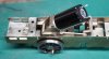
    Here are the parts for the gearbox, including the Gibson rear drivers bored and bushed and running true (see earlier post on how the sanitise your Gibsons).
    parts 1.jpg

    All routine machining, but at a small scale. A few workshop tips worth passing on for this kind of work...

    When parting off really small things in the lathe they do have a habit of launching at a tangent and finding their parabolic way to either the lathe's chip tray or the workshop floor. Then you have to decide whether it's quicker and less frustrating to just make another part or to carry out a search. Parting off with an old paint brush in the works pretty much eliminates that. Usually the part just pops off and is caught in the oily bristles. Worst case, at least you know it's in the brush somewhere. This shows the work held in a 3 jaw chuck, and care his needed to avoid a fight between chuck and brush, but for small work I usually use an ER16 collet, and then there's also space to place a small plastic tray on the cross slide under the tool. The brush catches 99% of the parts though. The brush is just an old 1 inch paint brush that I use to clear chips and swarf. It's got a bit sticky and spread out over time, which makes is it ideal for this. For a sense of scale the parting tool is 0.8mm wide.
    parting off brush.jpg

    Tapping very small threads without breaking the (expensive) tap and keeping the tap aligned to the hole can be a challenge. If I've drilled the hole on the mill or the lathe, this is how I follow up with the tap.
    M1 tapping.jpg
    In this case it's a M1 x 0.25 tap into a 0.75mm hole. These are the holes in the sides of the motor mounting block. The tap is held in a pin vice. The top of the pin vice handle is held loosely in a collet in the mill spindle. The collet isn't tightened to the vice, just squeezed up to a loose fit.
    There's no spring pressure on the tap like you'd get with traditional tap follower. Just the weight of the pin vice and whatever pressure you choose to exert with finger and thumb. As the tap advances into the work the spindle fine feed is adjusted to follow it down. This way you get a direct feel for how the tap is cutting. In the lathe, the pin vice is guided by a collet held in the tailstock, and the tailstock is wound out to follow the vice handle. It's helpful to turn a short section of plain diameter on the end of the pin chuck if it doesn't already have one.
     
    Bradwell WD 2-8-0 - the motor arrives, further complications, the drive train is assembled
  • Ian_C

    Western Thunderer
    The motor from High Level dropped through the letterbox this morning. It's a nice little thing. It runs very smoothly and quietly on straight DC. The 'worm between finger and thumb test' shows it has plenty of torque for its size. At the very lowest speed there's some cogging evident, as you'd expect, but that smooths out when there's a little load applied. I haven't tried it on DCC yet, but I will at some point. Altogether a splendid little motor, and I can see it'll suit some other projects in the queue as well.

    The motor comes with some M1.4 screws to hold it to your motor mount, but they're very short and only suitable for a sheet metal mounting. I had some M1.4 x 3 screws that were nearly long enough to work with my motor mounting block. Nearly. I had to make the counterbores in the mounting block a further 0.5mm deeper before I could fit the motor. Mercifully the calculated motor shaft to worm gear centres were spot on, so the gearbox was assembled as a trial.

    motor gbox assy 1.jpg
    motor gbox assy 2.jpg
    motor gbox assy 3.jpg
    motor gbox assy 4.jpg
    Don't worry, the drivers aren't fixed to the axle and quartered yet, that's load of faff and another story that'll get posted here shortly. It all runs smoothly and quietly under power and there seems to be plenty of tractive effort at low speed.

    Since the driven axle is suspended, the motor and gearbox need some kind of flexible torque reaction mounting to the chassis that accommodates vertical, lateral and rotational movement of the axle, but provides a close constraint on fore and aft movement of the gearbox. This is how it worked out...
    CAD 6 WT.jpg
    The torque reaction link (blue) is fixed to the gearbox using an extended screw in the motor mounting block. The other end is fixed to a bracket (green), which in turn is fixed to a chassis crossmember. This crossmember ends up covered by the front of the firebox so the bracket is not visible when the upper works are installed. To provide the flexibility and constraint the link sits over tiny rubber bushes (purple). Solid brass 'top hat' bushes sit inside the rubber bushes and provide the connection to gearbox and chassis. The rubber bushes are small slices of silicone rubber tube of 3mm O.D. and 2mm I.D. The link holes and the top hat bushes are sized to be a snug fit in the rubber. The rubber provides the necessary compliance and some sound deadening.

    It'a a performance and a half to get all this assembled to the chassis, but it does all go together...
    motor gbox assy loco trial 2.jpg
    motor gbox assy loco trial 3.jpg
    The firebox and boiler can be assembled over this, and it all seems to clear. Frustratingly I can't see how close the motor is to the inside of the firebox, but I expect I'll find out soon!

    A note on assembly. Even with a small motor (this one is 12mm diameter) there's no way to pass the motor through the chassis from below. The clear width inside the rear axle horn guides is a measly 9.8mm, and I don't fancy cutting back the horn guides and bearing blocks at this stage. Also as the wheels will be permanently fixed to the axle, all the gearbox gubbins is trapped on the axle forever, and that clearly has to be assembled to the chassis from below. The screws holding the motor to the the gearbox can't be accessed when the gearbox is assembled. The screws holding the torque reaction bracket to the chassis can't be got to when the motor is in place, and the chassis side prevents access to the forward link bush. Almost snookered.

    The only way to do this is to assemble the torque link to the chassis bracket, and then the chassis bracket to the chassis. The gearbox is assembled, the axle fitted and the driving wheels quartered, gauged and fixed The axle and gearbox assembly is fitted to the chassis from below, without the motor. The motor mounting block is then removed from the gearbox and fitted to the motor. The motor and mounting block can then be fitted back to the gearbox side plates in-situ, and the rear fixing for the torque link assembled at the same time (there's only just access to the lower motor mounting block screws with the axle bearing at the top of the horn guide slots.

    The only other way would be to assemble the motor and gearbox, minus the axle, and drop them into the chassis from above. Then attempt to thread the axle through everything and get the wheels gauged and quartered with the chassis all tangled up with the GW wheel press and the B-to-B gauge. Never a happy ending in my experience.
     

    Attachments

    • motor gbox assy loco trial 1.jpg
      motor gbox assy loco trial 1.jpg
      169.8 KB · Views: 6
    Last edited:
    Bradwell WD 2-8-0 - sledgehammer walnut wheel quartering
  • Ian_C

    Western Thunderer
    I've arrived at a very much not looked forward to milestone (millstone?) - quartering the rear drivers around the gearbox and bearing blocks. Can't do the squinting through the spokes trick on WD wheels, and I'm not convinced anyway...parallax, tapered spokes etc. The GW wheel press is too much of a handful (for me at least) with lots of clutter on the axle. Time to pull on the hair shirt of over-engineering and come up with a complicated way of doing it. Here's what I came up with...

    quarter tool 1.jpg
    The approach is to centre the wheels and axle in the 'V' and use accurately determined vertical and horizontal surfaces to set the crankpin positions, and thus the angular relationship of the wheels. In theory there are some problems with this since the wheel tyre surfaces are conical, so side to side freedom of the wheel set in the V when it is brought to the correct gauge would cause the wheels to rise or fall slightly. If the distance between the inside of the V's is close to the dimension outside of the flanges then the amount of wheel rise and fall from lateral slop in the fixture is very small and can be neglected. With the V's outside of the flanges the B-to-B can be controlled at any point you can conveniently get a gauge around the gearbox/chassis clutter. This set up can also accommodate RH and LH leads at any relative angle for any size of wheel (well, up to 7 ft diameter in this fixture - no good if you have a L&Y 'highflier' to quarter ). The downside is that it requires some calculation and some accurate measuring.

    quarter tool 2.jpg
    The main part of the tool was machined from a convenient nugget of aluminium (extruded bar offcut, so probably HE30 or similar). Care was taken to establish and work from the datum faces and machine the V's relative to them. To do this properly you'd really want to make it from steel and grind in the datum surfaces, but aluminium was to hand and easy to machine for a try out, and I don't have a surface grinder (yet). There's slight radius on the inside edges of the Vees to accommodate the radius at the root of the flange.

    quarter tool 3.jpg
    On one side there's a sliding vertical block with a face perpendicular to the horizontal base datum. That's used to set the position of one crankpin vertically above the axle centre. Its position can be adjusted by loosening an M3 socket head screw.

    quarter tool datum face copy.jpg
    The crankpin positions are set from 2 datum surfaces. Surface A is used to set the position of the vertical sliding block, which determines the position of the crankpin that's set vertically above the axle centre line. Surface B is the horizontal datum from which the height of the other crankpin is set.

    quarter tool CAD 1.JPG
    The tool was 'calibrated' before use by setting a gauge pin across the Vees and measuring its position relative to the defined datum surfaces. This was done on a granite surface table with a decent height gauge (could also have done with with gauge blocks and DTI if I'd felt the need for another decimal point). From these measurements the relationship of the Vees to the datum surfaces can be accurately determined, and then used to calculate crankpin positions. The WD wheel is shown above as an example. The diameter of the wheel in this set up is determined by measuring the tyre diameter at the point just before it transitions to the radius at the root of the flange, since that's what will sit on the Vees. The wheel diameter is drawn tangent/tangent to the Vees in CAD and the axle centre height found. For the Gibson WD driving wheels with a 1.6mm diameter crankpin the settings are -
    • Sliding block at 18.32mm from datum surface A (distance from datum to axle centre plus 1/2 of the crankpin diameter)
    • Lower tangent of opposite crankpin 16.78mm above datum surface B ( axle centre height minus 1/2 of the crankpin diameter).
    The sliding block position is set by a gauge block stack on the surface plate. The height of the opposite crankpin is set with a gauge block stack.

    quarter tool 4.jpg
    One wheel is fixed permanently to the axle with good old Loctite 601 and left to cure before setting up for quartering. This is it roughly set up with one axle loose before sliding in the B-to-B gauges. The axle length was determined previously by measuring across the wheels on a B-to-B gauge. Here's the 90 degree leading RH crankpin sitting in contact with the gauge block stack.

    quarter tool 5.jpg
    And here's the opposite side crankpin at top dead centre in contact with the sliding block.

    quarter tool 6.jpg
    Here's the final set up with B-to-B gauges in position. One Scalefour Soc Joe Brook Smith length of P4 angle iron, and one home made gauge to the same dimension sat on the gearbox. That way the wheels are gauged at roughly opposite locations to avoid the axial wobble you can get from only gauging the B-to-B one side.

    Setting up this whole shebang is a load more fiddly that it looks. Tweaking one thing tends to upset another, so it's a case of poking and prodding in ever decreasing circles until it all sits right. It takes much longer than the curing time of Loctite 601, so the final wheel is fixed to the axle with a smear of slow curing epoxy. Leave it over night for the epoxy to harden before removing from the fixture. One axle per day? Not really a constraint at my usual glacial rate of progress.

    How accurate is it after all of that effort? So far as I can work it out from my ability to measure what I've made, and an estimate of other possible sources of error I think I'll be within 0.5 of a degree of a 90 degree setting. The smaller the scale and the smaller the crank throw the more difficult it gets. To get better than this at 4mm scale really requires the ability to make and measure to around the 5 to 1 micron level (0.005 - 0.001 mm). As has been pointed out before, the quartering angle doesn't matter so much in absolute terms as long as all axles are consistent. Over the course of this project I have driving axles with at least two different quartering methods, so I'll soon find out if they're close enough.
     
    Bradwell WD 2-8-0 - my little pony truck and some DCC
  • Ian_C

    Western Thunderer
    The next step is to get a reliable running chassis off which all the other clutter can be hung.

    With the rear driving axle assembled and quartered, the chassis was wheeled and the coupling rods put back on. It took a little more easing of the crankpin holes than I'd imagined to get slow speed running without a limp. I think the cause of the sticky spot was down to variation in the crank throw on either the leading or trailing driving axles, the ones where I'd re-engineered the crankpins. To re-drill for the new crankpins I just optically centred up on the old crankpin hole. Since the bushing of the wheels to get the axles on centre had shifted the axle centre slightly, that means the crank throw also changed slightly. Not much, but just enough to make it tight at one part of each revolution. Obvious in hindsight - will take more care next time. The connecting rods were also...erm...connected and the bare 0-8-0 chassis powered up and down the test track with croc clips on the motor terminals. I was relieved to find that the chassis was able to find it's way round the 3 ft radius curve without drama, and that the leading crankpins did clear the inside of the cross heads while doing so. Sorry, no photos, but so far, so good.

    I never had worked out quite how Mr Bradwell intended the pony truck to be secured, beyond the tiny 14BA screw at the rear frame pivot. It is s tiny screw, and the pony truck hangs down and flops all over when the loco is lifted off the rails. I couldn't see that lasting very long. The pony truck needs to be fixed near the front as well. Here's how it worked out...

    Originally the pony truck was meant to sit on a folded up etched box forward of the cylinders. You can see it in the photo below, along with a bit of screw thread poking out. I'm guessing that a nut was meant to go over that to restrain the front of the pony truck. Well, the axle is right below it, so there's no way of fitting or adjusting that nut unless the pony truck wheels are removable, and that's not covered in the instructions.
    WD pony truck 1.jpg

    The fold up box was unsoldered and replaced with a turned truck support of exactly the same height, with a 12BA thread down the centre. Support soldered carefully to the chassis. As I'm typing this I note that Arsenal are already 3 down to City and it's not half time yet - you just knew that was going to happen. 6-0 at the final whistle, you read it here first.
    WD pony truck 2.jpg

    I made a brass block to mount an axle keeper plate, and epoxied that to the truck frame. I didn't want to risk soldering that lump and unsoldering the truck frame or upsetting the spring castings. It's barely visible on the loco and has the merit of adding a bit of mass to the truck.
    WD pony truck 3.jpg

    A small piece of lead was epoxied to the top of the truck frame as well. Not much room here, and need to be careful that the lead doesn't contact the chassis.
    WD pony truck 4.jpg

    The rear of the truck frame is fixed with the 14BA screw. I added a spacer sleeve and a washer under the head, so it's like a shoulder screw really, and can be tightened without trapping the truck frame. At the front there's another shoulder screwy thing that goes through the the hole in the top of the truck frame and into the threaded hole in the support boss below. There's plenty of clearance around the screw, so the only thing it does is stop the truck from separating very far from the chassis when it's lifted off the rails. 4-0 now.
    WD pony truck 5.jpg

    And finally the axle keep plate is fitted, which makes it all look a lot tidier. Another bit of technical uncertainty cleared up on the way to a working chassis.
    WD pony truck 6.jpg

    Having been somewhat won over by the magic of DCC on the S7 8F, I thought I'd have a go in 4mm as well. The DCC Concepts Zen Black decoders seemed to get decent reviews and be reasonably priced, so I bought a DCD-ZN8H.2 and a small 'stay alive' capacitor. The decoder was stuffed on top of the tender and jury rigged with power from some jump leads. Once I'd managed to update JMRI Decoder Pro, found the SPROG 2 and the right USB lead and remembered how to add a new loco to the roster I was able to run it back and forth on the 14 inches of mini test plank (although I suppose I ought to call it the 'programming track' now). The decoder will go in the tender where there's load of room now that the motor's been evicted. On the basic DCC set up it runs very well, although you have to have your wits about you on a 14 inch length of track when 'momentum' is switched on. I only have two minor DCC problems to solve: I can't see CV25 which is supposed to be the 'one step set up' CV on this decoder, and at start on speed step 1 there's a little lurch forward before slow speed running is established. I'm guessing some CV tinkering will fix this, once I 've understood it.
    WD DCC test 1.jpg

    I'm very pleased to have got this far. Now it runs well, I'm confident I'll be able to finish the build. Next step is to fit the spring wires to the axleboxes and assemble the valve gear . 5-0 at the Etihad now. And wet qualifying at Spa :)
     
    Loco storage box
  • Ian_C

    Western Thunderer
    Thought I 'd share this while we're waiting for F1 to start at waterlogged Spa. I got around to finishing the storage box for the S7 8F this morning.

    8F box 1.jpg
    It's made from odds and sods of wood. You know, those offcuts that you can't bear to throw away, that you never use, and they pile up down the far end of the workshop. The base is from a very nice piece of maple. There's a rebate 2mm deep and of track gauge width. The lid is from odd softwood planky bits, shoved through the thicknesser to get them to 10mm. Held together with white glue and some internal fillets. The foam lining is from medium density EVA foam. Easy to get small sheets on eBay (but never in the thickness you want). The little over centre catches were difficult to find, eventually found some from RS Components. There are rubber feet screwed to the underside of the base.

    8F box 2.jpg
    The wheels sit on the edges of the rebate. Quicker and less costly than making a length of track to sit on. The foam lining of the lid is from 6mm and 10mm thick foam sheets and the box size was calculated to allow the foam to sit close to, but not in contact with the loco when the lid is clipped on. If the box is handled carefully then the loco just sits on the base. If it is tipped or bumped the loco only has a couple of mm to move before it is supported by the foam. I'll see how it works.

    8F box 3.jpg
    And there's a fold down carrying handle on the top. Yes, I do trust the catches! Just need to stencil the number on the lid now - a further 6 months will elapse.
     
    Bradwell WD 2-8-0 - electrics done
  • Ian_C

    Western Thunderer
    Actually the next step turned out to be the electrics. After the usual amount of faffing around and head scratching, I think the electrics are now done. It's the usual story of little thought being spent on the subject early in the project, followed by a great deal of difficulty in making it all fit together and work later on. Definitely won't make that mistake next time - unless I do.

    The original plan for pick ups was to short out tender wheels on the LH side and loco wheels on the RH side. Power being taken between tender and loco which are opposite polarities (yes, the drawbar is non -conducting and made from Acetal). To that end I''d used shorting wires on the loco drivers and silver conductive paint on the tender wheels. When I replaced the front and rear driving axles I didn't fancy trying the shorting wire trick again, and to be honest I'm not sure how I got away with it originally when I first started the build. I thought about traditional springy wire pick ups on the loco or the tender, or both. Or maybe plunger pick ups on the loco. They all promised further complication in a rather odd and congested chassis design. Back to silver conductive paint then. I cleaned the backs of the right hand driving wheels and gave them a couple of coats of silver conductive paint, being careful to connect tyres to axles. The current path is: tyres - silver paint - axles - axle boxes - chassis. You'd wonder how reliable that was with oil films, clearances and moving parts, but it seems to work very well. The 'watch out' is that the chassis, motion and bodywork is also live to the RH rail and anything touching the tyres of the LH wheels will cause a short. I'll probably have to make some plastic brake shoes when I get to that stage.

    overall elec view.jpg
    The DCC decoder, the stay alive capacitor and capacitor control board are stuffed into a box made from scraps of plasticard. The decoder came with a NEM652 eight pin connector and that is held in a smaller box toward the front of the tender where the internal width and height reduces. The top of the tender chassis was plated over with a large piece scrap etch from the MOK 8F kit so the box had something to sit on (is this the only successful example of cross-kitting between 7mm and 4mm?). The box is held in position on the tender chassis by a small screw.

    loco tender connector.jpg
    The connection between loco and tender is through a small 4 way connector. You can buy these connectors on eBay or Amazon easily enough, but this one was from DCC Concepts and the female side of the connector is pre-soldered to a small PCB to which the wires are soldered. This arrangement makes it much easier to secure that side of the connector to the loco chassis. There's a hole in the PCB for a fixing screw, but lacking any way of fitting a screw here, I opted to epoxy the PCB to the chassis. The connector is small enough to sit beneath the cab floor. The wires cross over into the tender beneath the tender foot plate, taking the route previously occupied by the tender drive shaft. Only three wires need to cross the gap: power from RH rail taken from the chassis, motor 1 and motor 2. I'd have liked thinner, more flexible wire (like decoder wire), but the male connector comes prewired and so far as I can see it would be impossible to rewire.

    chassis power connection.jpg
    The power from the RH rail is just taken from the chassis by a brass terminal screwed to the chassis, straight back to the connector PCB. Simple innit? No wipers to fit and adjust, no friction, no funny scraping noises.

    motor connections.jpg
    Fixing the loco side of the connector permanently to the chassis makes it relatively easy to insert and remove the mating half, but it does make for some extra work. If the motor connections from the PCB are soldered to the motor tags then you can't remove the motor without unsoldering the wires every time, and that doesn't feel like a good idea. Therefore some small brass terminal blocks with 14BA threads are soldered to the motor tags and I made some tiny brass ring terminals for the end of the wires. The motor can now be removed and refitted without soldering.
     
    Bradwell WD 2-8-0 - Weight and springs and valve gear things
  • Ian_C

    Western Thunderer
    More fundamental mechanics to sort out - springs and weight. Bradwell provides independent springs for each axle box. They're essentially lengths of 0.32mm diameter spring steel wire simply supported at each end and supporting the axle box at the centre. What the instructions don't tell me is what the loco weight should be to match the springs and achieve the correct ride height. It's easy enough to calculate the effective spring rate using simple beam theory and the properties of the wire. (Dust off your engineering text books or surf to CLAG for an explanation).

    Some Scalefour folk seem to recommend weighting locomotives to 4 grammes per prototype ton. So for a WD weighing in at around 70 tons (possibly more if the typical WD cocoon of filth is included) the model should weigh around 280 grammes. So around 35 grammes weight on each driving wheel (neglecting the pony truck springs). That's a weighty model, but not outrageously so. Somewhere on the CLAG site I think there's a recommendation that a loco should ideally compress it's springs by around 0.5mm, that being enough to keep some weight on all the wheels when negotiating track irregularities (unless negotiating NCB sidings when 0.5m really doesn't cover it, and derailments would be prototypical - and then you'd need an army of Modelu workmen types standing around the mishap looking on while one bloke labours with packing timber and the big jack - digression, now back to subject). As it happens the WD would compress it's springs by very close to 0.5mm if it weighed 280 grammes. That's either a total co-incidence, or Mr Bradwell got his sums right. Probably the latter. In fact here's not much room to manoeuvre with springs at this scale. The stiffness of the a wire spring being proportional to the cube of the diameter, the steps between commercially available wire diameters make big differences to spring stiffness. It's quite likely that one diameter up and the springs become much too strong, and one diameter down (if you can actually find thinner wire) makes springs that are too soft. You can alter the length of the spring wire within the limits imposed by the chassis design, or you can change the spring material. Practically there's a choice between spring steel wire or phosphor bronze wire, with PB springs being about half the stiffness of steel, everything else being equal. So I'll go with the steel wire springs supplied with the kit and see how it works out.

    So how much weight needs to be added, and where? All the loco parts were gathered together and weighed on the kitchen scales, and that weight was subtracted from 280g. I need to add about 100g. I also want the centre of mass to be close to the centre of the driving wheelbase. There is space in the boiler, but if I put all the 100g in there the CoM would end up well forward. The only other space where a reasonable amount of weight could be added is the firebox, and that would have to fit around the motor and gearbox. Brain hurts, and I can't work this out on paper. CAD time again.

    centre of mass WT.jpg
    The weights are made from lead, shown orange in the screen grab. The boiler weight can be a simple cylinder of a size that can be fiddled into place through the firebox. The firebox weight has to sit up abovethe motor and back against the rear firebox former. Both weights have to fit up through the lower aperture in the firebox, so that limits their width. The basic shapes were modelled and tweaked until the combined centre of mass (the little red, green, blue axis arrows in the pic above) sat between axles 2 and 3. When you're designing something to a weight limit it's always really hard to make things light enough without spending silly money. And conversely when you're trying to get something up to a target weight it's hard to find space to add mass. It just about works with lead weights. If you were struggling to get the mass in, an alternative would be to use tungsten.
    Density of Lead 11,343 kg /m3
    Density if Tungsten 19,600 kg/m3
    Density of Tungsten carbide 15,800 kg/m3
    Density of Uranium 19,050 kg/m3

    Yes, you can get Tungsten on eBay and Amazon, in the form of TIG welding electrodes, up to 10mm heaven help us, and expensive. Discarded milling cutters would be a source of Tungsten carbide, but you need diamond to cut it. Uranium isn't anything like as heavy as I'd imagined, you can't get it on Amazon (yet), and there are probably other good reasons for not using it.

    When the size and shape of the weights was settled, off the the workshop to make some. I cast two blanks using a length of thick wall steel tube bored to a diameter slightly larger than the weights. Put a slight taper on the inside diameter otherwise you'll not get the lead out when it's cooled. I know, I tried before adding a taper! This is a great opportunity to use up all those odd scraps of lead you can't find a use for but can't bear to throw away. Just heat up the tube and drop in the bits & bobs, scrape the scum off the top and let it cool.
    cast weight.jpg

    Some very easy machining later and I have two weights. Both were carefully positioned and fixed with plenty of epoxy. The boiler / firebox sub-assembly has some heft to it now.
    machined weights.jpg

    ------------------------
    Change of subject, in case it wasn't obvious.

    A pox on you Mr Walschaerts. You clearly didn't think about the 4mm modeller when you invented your eponymous valve gear. The WD gear is etched dead to scale and surprisingly delicate for the rough and lumpen WD. See earlier post about making the parts. t's a right fiddle to assemble. Getting the clearances for sufficient articulation at all the joints requires lots of micro fettling. I have an escapement file ground down to 0.5mm thick which is handy for cleaning out the forked joints. 0.55mm brass pins had their heads reduced by file in a mini drill to make the pivot pins. Soldering the pins in place has great disaster potential, ending up with everything soldered solid isn't unknown. I do it by using aluminium foil as a solder mask and heat sink. The traditional method is to use paper, but aluminium foil is much thinner, resists flux and solder, and is easier to get out cleanly afterwards I find.
    valve gear pin assy 1.jpg
    valve gear pin assy 2.jpg
    The foil is inserted on the side of the joint where the pin will be soldered. I use a tiny blob of paste flux (which doesn't tend to migrate through the joint as much as liquid flux) and a tiny sliver of 145 solder which is held in place by the flux. The pin is then heated with a soldering iron about 5mm from the joint, and when the flux boils and the solder melts at the joint the iron is removed pronto. Works nine times out of ten, which is to say that I'm bound to end up soldering one joint solid on a project like this - which I did.

    valve gear nearly complete.jpg
    Here is one side mostly assembled. Just the return crank to work out, and it'll be a pig. I chose to set it in about half forward gear so the valve spindle moves when it's running. It'll be correct about half of the time I guess. The most difficult part of this assembly is where the combination lever , radius rod and valve spindle meet. You really have to work out the clearances around the valve guide casting before you try and assemble things. In particular make sure there's enough of a gap between the 'horns' of the guide for the spindle forks and the pivot pin heads to move freely. Oh, and I'm really sorry about the huge screw holding the coupling rod to the front crankpin, I can't think of any other way to make it work in S4. Seems to be sitting slightly too high on the springs though doesn't it? Hmmm..........
     
    Last edited:
    Bradwell WD 2-8-0 - the return cranks
  • Ian_C

    Western Thunderer
    I know I'm not the first person to have wondered how to make removable return cranks that end up in the correct angular position every time they're installed, but there's little written about it in the reference works on my bookshelf. The late , great Guy Williams hardly mentions it in either of his Wild Swan books and Geoff Holt advises to solder the crank to the end of the crankpin, which is no help if your crankpin is secured from the inside of the wheel, as they often are in 4mm. So, another design challenge, and back to the CAD screen.

    The cyan item is the steel crankpin, as described in more detail in a previous post. It's 1.6mm in diameter and threaded M1 x 0.25 down the centre. In this case it's only half the crankpin. The other half is the green top hat bush that carries the return crank, also threaded M1 x 0.25 through the centre. There are thin washers, in orange , to space the coupling rod off the wheel and the connecting rod off the coupling rod. The return crank is the etched component from the kit, and the little pink boss is to thicken up the crank at the end where is will be threaded M1 x 0.25 for the eccentric rod pin. This way the eccentric rod can be disconnected from the crank to allow the complete cylinder and valve gear assembly to be removed, and the crank can be unscrewed from the wheel to allow the connecting rod and coupling rod to be removed. The eccentric end of the crank arm on the WD has a 14" crank throw and is timed at about 95 degrees behind the crankpin. Interestingly it doesn't quite work out that way on CAD, and I think it is because the etched crank arm centres are a little short. But not to worry. There's no practical way of timing the thread on the top hat bush to land the crank arm in the right position, so the arm is soldered to the bush once it's tightened to the crankpin thread.
    WD return crank design 1.jpg

    Make some parts. The wheels here are the original Gibson wheels that have been sanitised and trued with a brass axle bush (previous post etc...). The crankpin holes were drilled out at exactly scale 14" throw this time, rather than drill out the existing hole to 1.6mm. Interestingly (or not) the moulded crankpin holes in the Gibson wheels were not quite a 14" throw, which probably accounts for some of the quartering challenges previously where I had a mix of some wheels with the original Gibson crankpin position and some with an accurate scale 14" throw. Parts are straightforward lathe work, albeit quite small.
    return crank parts.jpg
    Here's a wheel with the half crankpin installed, and with a length of M1 x 0.25 thread fixed with Loctite 601 high strength retainer. That part needs to stay put when the crank arm is screwed and unscrewed.
    crankpin 1.jpg

    Same wheel from the inside. Note the crankpin bush doesn't contact the axle bush. Life's simpler if there's no electrical contact here with this pick up system.
    crankpin rear.jpg

    Crank arms with the tiny boss silver soldered in place, so that they don't become unsoldered when the arm is soldered to the crankpin boss. Both the inside of the arm and the outside of the top hat boss are tinned with 145 degree solder. One of the top hat bosses is tightened to the crankpin thread ready for soldering. In passing, I've started using a small rectangle of medium density EVA foam to do assembly work on in place of the usual cutting mat. I find that small parts don't roll away on the foam, and if dropped on the mat they just stay where they land.
    return crank assy 1.jpg

    The thread stops a little short of the top of the thread to reduce the chances of solder getting to it. A smear of grease on the thread also helps.
    return crank assy 2.jpg

    The arms are positioned by eye and held in place with the tip of a scalpel blade, then sweated to the crankpin bush with a quick, hot iron. Now the arms will screw on tight in the right position every time. They will be specific to the left and right sides, so a small L and R is scribed on the inside of the respective arms.
    return crank assy 3.jpg

    All that's left to do is put the axleboxes on the axle and quarter the wheels. I'm hoping that this won't mean another chapter of quartering and coupling rod wars if these wheels don't closely match the previous set up.

    It's worth noting that on the prototype the crankpin on the driving axle was 6-1/2" to 6" in diameter, or 2mm to scale. So the 1.6mm crankpins here are slightly undernourished. Things would have been a little easier and slightly more robust with 2mm crankpins. Next time. You can also see that the moulded crankpin boss is not really large enough for a 2mm crankpin, so although the Gibson wheels look quite nice they're not 'that' accurate. Now I examine some WD photos it looks as if all of the wheel centres were cast to the same pattern, and the crankpin boss appears significantly bigger than on the Gibson mouldings. But if I hadn't mentioned it who'd have noticed?
     
    Last edited:
    Bradwell WD 2-8-0 - eccentric rod pin
  • Ian_C

    Western Thunderer
    Hoping this is the end of the valve gear episode, but until I see it all working, who knows?

    Here's a teeny weeny pin and bush for the eccentric rod, cruelly enlarged. The bush is turned from brass. It's probably the smallest turned part I've managed to make so far. It's 0.9mm long, 1.2mm O.D., 1.0mm I.D. Being idle, I only made two of them, and so far I've not lost one. Breathe on them the wrong way and they're gone! The pin is made from a length on M1 x 0.25 steel screw with a flange soldered on before filing a hexagon on the end of the protruding thread. Of course I'm left with a big hole in the centre of the crank etching that I don't need, so that'll have to be filled at some point.
    eccentric rod pin.jpg

    If this was watchmaking these parts would be considered unspeakably crude. So how do they make small parts to such a high standard? Clearly there's scope for improvement.
     
    Bradwell WD 2-8-0 - working valve gear and motion, springs, brake shoes
  • Ian_C

    Western Thunderer
    This really is the end of the valve gear and motion episode (unless it turns out not to be).

    Together and apart many times to find and sort out little niggles and clearances. Eventually it all fits together and works. Here it is with the foot plate and cab just dropped in position. Very carefully applied medium strength thread lock is necessary to prevent some of the small threaded fasteners unscrewing when in motion.
    WD valve gear assy 2.jpg
    WD valve gear assy 3.jpg

    Just to amuse myself I put together a short video of the valve gear of the loco in motion on the test track. I'd felt an urge to learn a bit of Adobe Premiere Pro and this seemed like a good enough excuse. Turned out to be a huge distraction and I haven't done any actual modelling for a couple of weeks. The sound isn't DCC sound (no sound decoder fitted), but odd sounds scraped off recordings and other videos. Genuine WD clanks! It's not Spielberg but it was fun and I've learned a lot in doing it. Can't get anything to upload to You Tube at the moment, but no problems with Vimeo...

    In other news, the steel springs, although theoretically correct, just weren't workable. I found it impossible to get the loco to sit straight and it always felt as if the springs were too stiff. In the end I substituted them with springs made from phosphor bronze wire, which allowed the loco to sit down more comfortably. There's still a workable amount of suspension travel and it feels less 'bouncy'.

    Thinking ahead to brake gear. Having brass brake shoes always seems electrically perilous to me. So far as I can tell the WD used exactly the same pattern brake shoes as the Stanier 8F. I used the CAD model of the brake shoe that I created for the 7mm 8F and scaled it to 4mm (I suppose that's called 'leveraging the design asset' in work speak). To make a 3D print reasonably economical I cloned the brake shoe up to twenty sets of eight shoes. More brake shoes there than I'll ever use in this lifetime.
    brake shoe CAD.JPG
    Brake shoes CAD 1.JPG

    In the end I had them printed by Shapeways. Certainly not the cheapest, but you always get a consistently good quality if you stick to their design guidelines, which I haven't always found to be the case with 'bloke in a shed' type suppliers. Came out pretty well. You can just see some layering on the close up photo, but that'll be removed with a lick of fine wet & dry.
    brakes  whole print.jpg
    brakes close 8.jpg
     
    Last edited:
    Bradwell WD 2-8-0 - Brakes that really do bring you to a stop...
  • Ian_C

    Western Thunderer
    ...but for the wrong reason!

    After the valve gear I decided to have a go at the brakes. Cutting parts from the etch for the first time in ages felt like progress. It's a bit of a fiddle because the brake hanger brackets have to be made up from some small parts. Two etched parts, both with push through rivets, one with a double bend, and a length of 0.7 mm diameter brass wire.
    brake parts 1.jpg

    Bradwell suggests making them up before soldering them into position on the chassis. I couldn't imagine being able to solder them to the chassis without unsoldering the brackets themselves, so I elected to silver solder the brackets . Here's a pair assembled around a length of wire which is pressed into a hole drilled in the heat proof block. The cruddy stuff is a tiny amount of silver solder paste before being heated. You have to be careful with the flame on small parts as it's easy to overheat them. I managed to melt one, so a replacement had to be made from scratch.
    brake parts 2.jpg

    These are the brackets silver soldered before cleaning up. Well, the one bottom right has been cleaned up already.
    brake parts 3.jpg

    All cleaned up. A short length of wire is left projecting from the back to locate in the holes in the chassis sides. You'll see that a gap has been cut in the wire between the inner and outer legs of the bracket. That is to enable the brake hanger to be slid up into the gap and hooked onto the wire stub. That way the whole brake sub assembly can be fitted and removed with out needing fasteners.
    brake parts 4.jpg

    Here's the brake rigging beneath then loco that connects the brake hangers to the brake cylinder beneath the cab. Straightforward N/S etch and solder. A little simplified but you'll not see much of it.
    brake parts 5.jpg

    The brakes are made up by filing off the outline of the brake blocks from the etched hangers. The blocks are pinned to the hangers with short lengths of 0.5 mm wire.
    brake parts 6.jpg

    This shows a bracket located on the chassis.
    brake brkt clash 2.jpg

    And here's where it all goes wrong. You can see that the bracket is long enough to contact the connecting rods. No amount of finessing is going to sort that out. The only solution is to make shorter brackets. And since I silver soldered them together there's no chance of unsoldering them to recover some of the parts :headbang:. Not sure I'm in the mood for making eight of these from scratch at the moment.
    brake brkt clash 1.jpg
     
    Bradwell WD 2-8-0 - injectors (welcome back threadmarks)
  • Ian_C

    Western Thunderer
    On to the injectors. Yup, you can get a whole chapter out of the injectors. The prototype was equipped with two identical Davies & Metcalfe No 11 injectors RH pattern, fitted with No10 cones. The Scalefour Society says I should be 'getting it all right', but I guess I can still keep my membership if I don't bother with the cones. The kit was supplied with a couple of very nice brass injector castings that only needed the pipe holes drilling a bit deeper. Squinting at the GA drawing suggests that the injector pipework was of two diameters that scale to approximately 0.7mm and 0.8mm. My horde of copper wire has been mostly looted from electrical cable and naturally none of it was a suitable size. Amazon to the rescue of course, and it is possible to buy small reels of 0.7mm and 0.8mm copper wire for making low rent jewellery.

    First job was to make up the bracket that supports the injectors. There are half etched rivets to represent the injector fixing bolts, but they look a bit too smooth and rivety whereas the bolt heads are distinct on most photos. They were drilled through 0.5mm and stubs of brass wire were silver soldered in place and filed down. Definitely more bolty now. The injector castings were soldered to the bracket with a high melt solder.
    WD injectors 1.jpg

    The etched bracket spans the chassis and it's a bit goofy and bendy, so Bradwell advises reinforcing with wire on the inside. You can sort of see the wire trying to keep out of focus in this photo showing the inside of the injector.
    WD injectors 2.jpg

    And here it is ready to fit to the chassis.
    WD injectors 3.jpg


    I also added to the side of the chassis the triangular brackets that support the footplate. Now there are things sticking out of each side of the chassis it's more difficult to work on the chassis and easy to bend the things. The front brackets, just behind the cylinders, are particularly vulnerable with a big hole etched through them. But not to worry, as I found out that it's impossible to fit the cylinders to the chassis with these brackets in place, so off they came again. I'm not sure I'll miss them in that dark and filthy corner. Maybe I'll fix them to the underside of the footplate instead. We'll see...
    WD injectors 4.jpg

    The injector steam pipes from the cab end up level with the chassis top surface and terminate in thin air. To give them some support I added two plates (green arrows) from scrap etched. I'm confident you'll not see these plates under the footplate. The pipes passed through holes in the plates and were cut and filed flush after soldering. The boiler feed pipes running forward along each side beneath the edge of the footplate are very visible, but the problem is what to fix them to. If you fit them to the footplate the end connecting to the injector is unsupported. And if you fit them to the injector you can't secure them to the footplate because that's part of the boiler assembly and has to be removable from the chassis. My solution was to add some more small pieces of scrap etch (red arrows) to reinforce the weedy triangular brackets on the side of the chassis and support the injector pipes. The beautifully crisp white metal sand box castings were epoxied to the chassis at this point. There's no positive location for them on the chassis so take care to position them accurately.
    WD injectors 5.jpg

    Here are the feed pipes soldered to the new brackets. The pipes actually dive inside the motion bracket assembly on their way forwards, but again they can't do this the model as they would make it impossible to remove the cylinder and motion assembly from the chassis. I chose to terminate the pipes short of the motion bracket and gamble that it won't be noticeable under the footplate. They do end in thin air but they're close enough to the chassis not to be very vulnerable. I hope.
    WD injectors 6.jpg

    Here's the injector pipe work seen from below. I should mention at this point that the copper wire, although appearing to be plain wire, actually has a thin and very tenacious coating of something. That's a pain because it all has to be removed before soldering. Whatever it is it's heat proof, solvent proof and really takes some shifting with an abrasive pad. You can also see the diagonal stays bracing the injector brackets to the chassis. The instructions have a couple of decent sketches to clarify the injector pipe routing.
    WD injectors 7.jpg
    WD injectors 8.jpg

    The RH side view. The injector overflow pipe on this side of a WD has two variants. There's one that simply exits the injector and has a short downwards pointing section. And there's this one that loops back under the injector and is secured to the injector bracket with a small strap. This type seems to be the more common on BR locos. I've just noticed that I've missed two small straps that secure the pipe to the footplate. A couple of strips of brass shim sweated to the pipe should fix that.
    WD injectors 9.jpg

    LH side, also missing the support straps. The pipe neatly hides its support brackets.
    WD injectors 11.jpg

    I couldn't resist turning up a couple of tiny doodads to represent the pipe unions.
    WD injectors 10.jpg

    Next job is the sanding gear, which is bound to be a struggle.
     
    Bradwell WD 2-8-0 - sanding gear
  • Ian_C

    Western Thunderer
    'Sanding gear' isn't an anagram of 'gnashing rage', although it should be. I had to have two laps around the sanding gear to arrive at a workable solution.

    sanding parts 1.jpg
    The brackets that support the sanding gear on the WD are a delicate confection of strips and plates and angle iron. It's beyond me to model that lot to scale in 4mm, and it would not be sufficiently robust to survive handling during the rest of the build or in use. So what follows is a bit of approximation and bodgery. After some staring and head scratching I decided to make the sanding pipe brackets from strips of 0.4mm N/S, 1mm wide. The sand pipes scale to about 0.5mm and are from brass wire. Some tiny brass turnings represent the pipe fitting near the support brackets.

    first attempt.jpg
    The pipes and brackets were eventually fiddled into place and soldered to the inside of the chassis. At that point I was congratulating myself on how relatively easy it had been, until I realised that that it would be impossible to fit the brake gear because the cross beams pass through the gap between sanding pipe and support bracket. Also with the pipes in position it proved impossible to remove the 3rd axle from the chassis. Oh well! Unsolder it all and think again.

    sanding parts 2.jpg
    The solution I adopted was to make the two forward most pairs of sanding pipes and brackets individual, removable parts that could be slipped over the brake beams and fixed by a small screw. The rear sanding pipes on the 3rd axle don't get tangled in the brake gear so they can stay as they are. More little brackets from scraps of N/S. The screws are M1.2 x 0.25. These small steel screws are dirt cheap on Ebay or Amazon. You can get a selection box with hundreds of the blighters from M1.2 up to M2.5 for not much. I find these small Philips head screws much easier to work with than the typical B.A. slotted head screws.

    fix by screw 1.jpg
    One was made up and fitted to test the theory. The hole was marked on the chassis and tapped M1.2. Luckily you can just get the screwdriver past the brake beam and onto the screw head.

    front sanding.jpg
    The pipes pass pretty close beneath the brake gear. I've left the end of the pipes a little further away from the wheels than is prototypical in order to reduce the risk of electrical shorts due to suspension movement and side play. Doesn't look too bad.

    sanding axle 1 beneath.jpg
    The brake gear is fitted first before the sanding pipes. Here's the first axle with everything in place.

    sanding axle 3 beneath.jpg
    And here's the third axle.

    sanding LH side.jpg
    And here's how it looks when it's all together. Enough authentic clutter down there to fill the gaps and attract the obligatory WD coating of oily filth. The odd looking vertical pipe in front of the injector is the vacuum pipe and water trap, a rather splendid little brass casting being supplied with the kit.

    What's next I wonder? Maybe the AWS gear.
     
    Last edited:
    Bradwell WD 2-8-0 - big bits coming together at last
  • Ian_C

    Western Thunderer
    With most of the difficult work out of the way (and yes, doubtless I'll eat my words a few more posts down the line) I figured it was time to put the upper works together.

    There's provision to fix the cab to the footplate and the back of the firebox with screws. That's handy, as it can be accurately located and used to get the exact position of the boiler without having to fix it permanently in place. Some fettling was required to make the smokebox sit down nicely on the saddle casting. The steam pipe exit location on the smoke box didn't quite line up with the corresponding holes for the steam pipes in the footplate. Maybe only half a mm but enough to make them look wrong when seen broadside on. I never did fix the smokebox into the front of the boiler as it's a perfect push fit and I thought it would be better to leave some adjustment there, both longitudinal and rotational. I carefully filed back the front edge of the boiler until the smokebox was far enough back for the steam pipes to line up. I didn't fancy trying to solder the smokebox to the saddle so I fixed it in position with epoxy. The elastic bands hold it tightly together while the epoxy cures. The epoxy also neatly fills any gap between smokebox and saddle and the surplus can be easily scraped away when cured. The firebox was easy enough to tack to the footplate just in front of the cab. Still needed the 100W iron as there's plenty of material to soak the heat away. There's no turning back now! You can see the mess I made of the firebox wrapper just in front of the washout covers. I've filled the divots with low melt solder and smoothed it the best I can. The reflected light makes it look worse than it is and I'm hoping that the kink in the handrail here plus some weathering will disguise it. Hoping...
    boiler to footplate.jpg

    The steam pipes were gently filed to a tidy fit and soldered in place at the footplate end only. No point trying to solder them to the smokebox as it would be a difficult joint and a devil of a job to clean up any stray solder. As is tradition enough parts were flung together to get an idea of how the loco is shaping up. The tender will be closer coupled than this when it's properly assembled. A lot of detail to add, but it's definitely a WD now.
    progress assy 12-2-22.jpg

    Gently frosted leaves this morning. Not spring here just yet.
    frosty leaves 1.jpg
     
    The 'no update' update
  • Ian_C

    Western Thunderer
    No work has been done on the WD since the last post. If you like you can stop reading now. A lot of other vaguely related stuff has happened. Time was obviously invented to prevent everything happening at once but it doesn't seem to have worked.

    My conscience gradually got the better of me and I was feeling obliged to build the next stage of the long running fitted kitchen saga (ten years and running). Having sacrificed some modelling time to design some kitchen I realised that it would be a good idea to replace the planer thicknesses blades before processing a load more sawn oak. Changing and setting the blades was an afternoon's work once the new blades arrived, but when I set the machine up to try them out I found that the thicknesser feed was making an unusual noise. On removing the cover from the feed mechanism I found that one of the drive pulleys had disintegrated. The machine has a most Heath Robinson arrangement of flat belts, V-belts, gears and chain sprockets to take a drive off the end of the cutter block shaft and reduce the speed to drive the feed rollers, almost as if the designer had set out to use something from every page of the industrial drive components catalogue on his desk. Damn - need a spare pulley. Unfortunately Scheppach stopped making the machine years ago and by now there are few spares available. There's no way I'm scrapping the whole machine for that so I had to make a replacement pulley from scratch. Of course that turned into a performance since the V-belt on one part of the pulley was an odd section and I couldn't buy an off the shelf gear for the other part. I'd been intending to get a proper rotary table / indexing head for the milling machine for ages, and the need to cut a gear was the clincher. Gear type identified, involute gear cutter ordered and crash course in gear cutting followed. The original pulley was a low quality die casting, so badly aged that you could break it into pieces by hand. The new gear was cut from mild steel bar. The V-belt pulley was turned from a slice of extruded aluminium round bar. The two were a transition fit with some Loctite retainer. Works beautifully.
    gear cutting .jpg
    scheppach pulley.jpg

    However, no return to kitchen design or even modelling. Some years ago we bought a couple of Velux window kits to add some natural light to the smaller upstairs rooms. One was installed a few years ago when the extension was built, the other window kit has sat taking up a load of space at the end of the workshop ever since. After a rough winter we thought it would be a good idea to have one of the more weather beaten roof pitches stripped and re-tiled, and at the same time have the Velux fitted. Quick job you'd think. Builder said two days, then didn't turn up on the day. The roof was fine in the end but the hole in the ceiling for the Velux must have been made with a bazooka. Tidiness isn't a thing with some tradesmen. The real purpose of the Velux was to have natural light over the modelling bench (your persistence has been rewarded, there is a modelling connection). It's always been a gloomy corner and suffered from damp some time back when the roof valley got blocked with autumn leaves. So it seemed like an opportunity to sort out that corner of the room. With old houses decorating work turns into minor building work which then escalates as you peel back the layers.
    velux 1.jpg
    Hole around Velux tidied up and expanding foam fired enthusiastically into the messy voids. Many spiders made homeless. Crumbly plaster on adjoining wall stripped off. And, as we find occasionally in this house, a couple of bricks were made of oak. Presumably they were incorporated in the wall originally to provide fixing points for something. Often the wood is rotten. In this case damp from the leaky roof valley finished it off. A suitably sized antique brick and a half from the garden was mortared in.

    velux 2.jpg
    Reveals constructed around Velux and plastering completed. Scabby lining paper over the lath and plaster ceiling was removed and the ceiling sanded and skimmed. New lining paper going back on. At this point I'm contemplating taking down all of the lath and plaster ceiling and replacing it with Thermaline insulated plasterboard, but I come to my senses and don't escalate further. Also thinking that the old laminate flooring should be replaced while the room is in a state of chaos. Come to my senses again. Just finish what I started otherwise it'll be endless.

    velux 3.jpg
    And about 10 litres of white emulsion finished the job. Ended up painting the whole room though. Still got blinds to fit. Amazing the difference natural light makes to a room. It's a lovely space now and I can move the modelling bench back into the corner soon. Looking forward to getting on with the WD again...except...

    ...there's another half done job that got interrupted by the builders and I need to finish that off to get the workshop back into a useable state. I bought a 100mm precision vice a while ago to replace the Indian 'value' vice that I usually use on the milling machine. It was OK - ish - but every time it was taken off and replaced it had to be indicated back in, and it was itself a bit geometrically challenged. It made precision work difficult and time consuming. The mill is trammed very carefully to the travel but the bed isn't exactly a level playing field. I made a fixture plate out of 15mm thick 275 grade steel plate and fly cut it in situ so I know the surface of the plate is perpendicular to the spindle axis. It's plain structural steel plate so it starts off with a mill scale surface and isn't particularly flat. Also since it's a rolled product and not normalised it has an amount of residual stress which is released when the surface is machined off. I took off the mill scale surfaces with a carbide face mill and then made a couple of passes on each side with the fly cutter to level out the curvature. 74 M8 holes were drilled and tapped (by hand!) at 25mm centres for fixturing. When it was bolted in place on the machine bed a final finishing pass was taken to get a perfectly flat surface.The plate was dowelled to the machine bed so it can be removed and replaced in exactly the same position. The vice has key slots on the underside and these can be used to key the vice to the fixture plate. A couple of steel keys were made to fit precisely in the slots (and yes, that had to be done on the 'value' vice, very , very carefully). The matching key slots were then milled into the fixture plate. Before I milled the key slots in the fixture plate I took a diversion and stripped the table and saddle assembly, cleaned everything, adjusted the lead screw backlash and re-fitted and adjusted the gibs. In theory when the vice is clamped to the fixture plate it'll be absolutely true to the X and Y axes and level in the X-Y plane. As it turned out the vice is good to within about 0.005mm in X, Y and X-Y across the width of the vice. I'm now able to reference the workpiece directly off the vice and not have to indicate the work after every move. Better quality work and much time saved. Very happy with that and about as good as it'll get on a machine like this.

    The learning is that you can do precision work on even a low cost Chinese hobby milling machine if...
    1. You're prepared to completely strip and rebuild the machine before you use it.
    2. You can do enough measuring to find the machine's geometrical errors and work out how to correct them.
    3. You're prepared to invest some time, effort and money in setting up and workholding.
    vice 1.jpg
    vice 2.jpg

    And after all that I still have to make kitchen part 2, although I'll probably time share that work with the WD. So maybe I'll post something model raiwayish here soon.

    But hang on...I've just ordered a load of parts to make a bench top CNC milling machine...
     
    Last edited:
    Another no-upate update - and season's greetings
  • Ian_C

    Western Thunderer
    I'm shocked at how long it is since I last posted any modelling content. I've not given up on railway modelling, but I have been massively diverted this year. Groundworks and new greenhouse in the spring, kitchen part 2 in the summer overlapping with DIY CNC machine ever since.
    grreenhouse 1.jpg

    kitchen 2-1.jpg
    kitchen 2.jpg
    CNC 1.jpgCNC 2jpg.jpg

    The plan is to use the CNC to machine model parts. I have it in my head that I can machine 7mm driving wheel centres directly on this machine. It should be capable of working with very small cutters. We'll see. I'm not intending to chronicle this build on WT, but once I'm up and running I'll post some relevant CAD/CAM/CNC in the appropriate part of WT.

    I'll get back to the P4 WD in due course. Meantime season's greetings to all.
     
    Top