Thanks Tony.
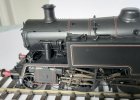
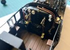
I had to take off the centre part of the roof to facilitate drilling holes to fit the slacking pipes so I took the opportunity to take an image of the cab interior.
Here's the water sieve made from styrene rod and card, with copper feedpipe and mounting pin.
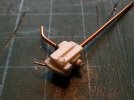
After painting ready for fitting with the mounting pin cut to size. I made it overlong to make it easy to hold for painting.

Here the sieve has been mounted on the underside of the tank.
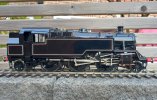
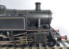
This image shows the slacking pipe on the rear of the cab and the proximity of the sieve to the rear coupling rod at the top of the stroke. As well as prototype images of the real thing, I measured the sieve on my MOK standard 4 tank to get the dimentions. It lacked clearance when trial fitted so I had to slim it down a bit with the file, but it passes muster.
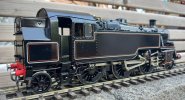
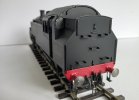
After having spent time fitting the speedometer, I couldn't find any evidence that my chosen prototype (82028), one of four allocated to the NE region when new, were speedo fitted in the early 50s, so I've removed it. The marks on the rear bunker panel is just residue from the lining adhesive that will be cleaned of before varnishing.

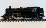
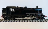
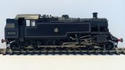
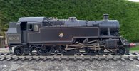
My brother dropped off the spare Fox lining transfers tonight so I will fill in the missing areas on the drop plates. There are some curves as well so hopefully I can improve the reverse curves at the bottom of the tanks. This comparison with an Internet image of the excellent Lionheart model shows what a big difference it will make if I can correct it.
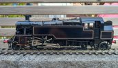
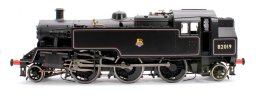
No. 19 was from one of the earlier batches fitted with fluted coupling rods
Cheers,
Peter