You are using an out of date browser. It may not display this or other websites correctly.
You should upgrade or use an alternative browser.
You should upgrade or use an alternative browser.
readingtype’s workbench
- Thread starter readingtype
- Start date
RCH wagon
readingtype
Western Thunderer
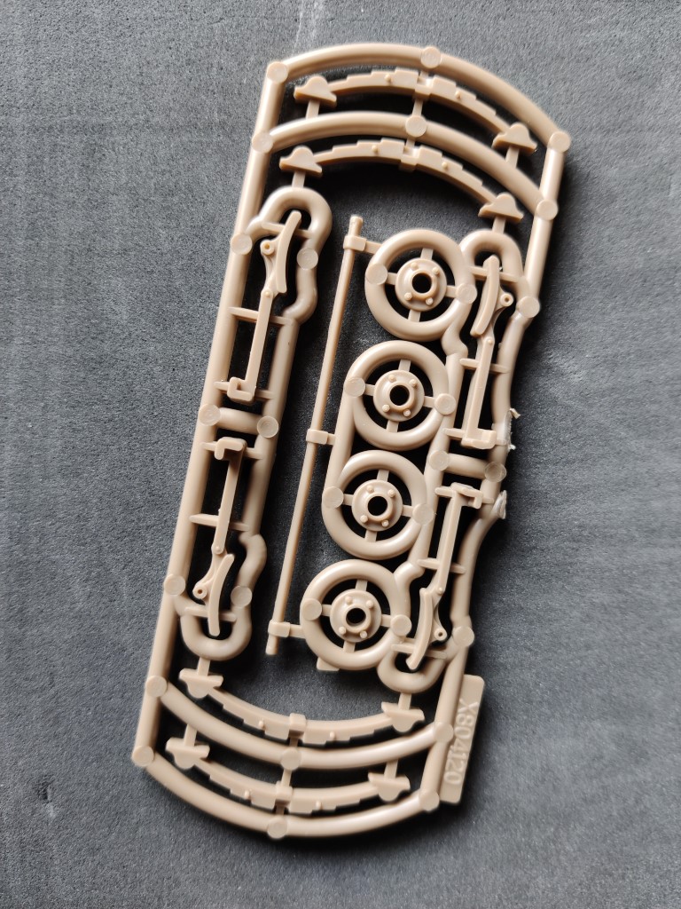
And meanwhile here is one of the most interesting sprues I have seen. It's not only interesting to look at (compact, but lots of channels too -- why?) but it is also well choreographed, as it's the opening act of the kit that it belongs to. Just to make a small inroad and destroy its perfection I'm going to take the four circular items in the middle out and see about fitting them to the assemblies they are part of. To further flog the operatic metaphor: we are shifting scales.
Hunslet DH cab
readingtype
Western Thunderer
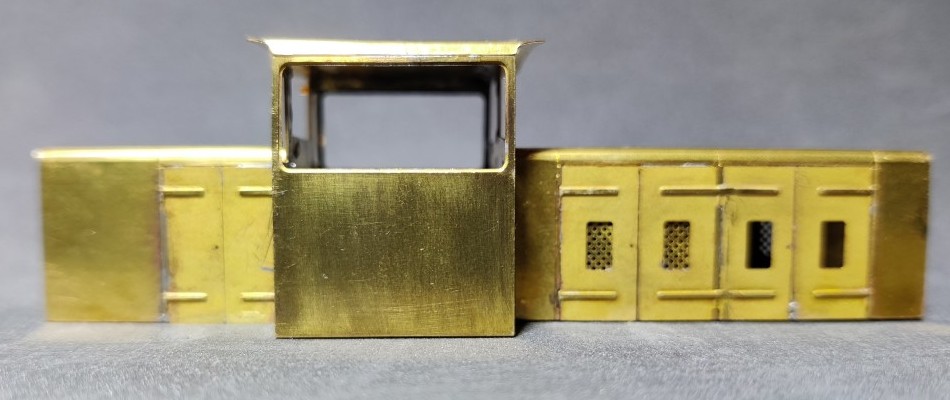
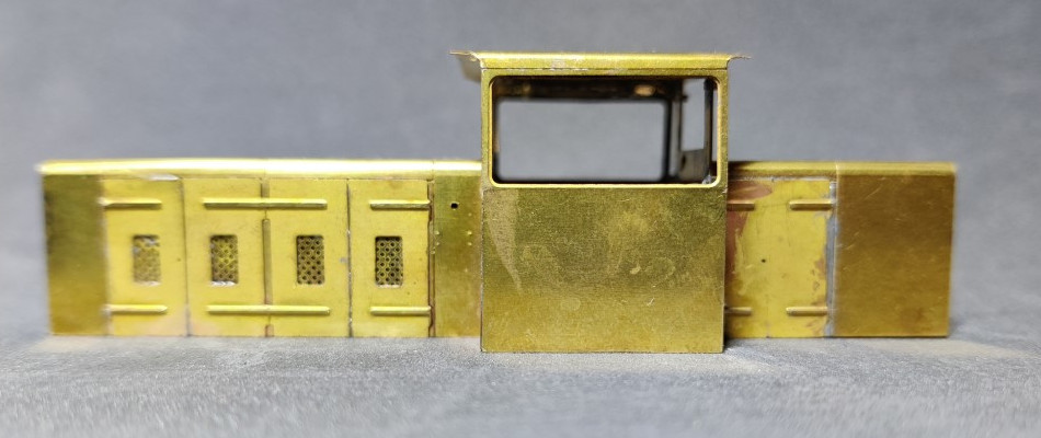
This evening I fitted a larger bit to the iron and poked the solder seams along the inside of the cab roof.
The solder was very willing to melt and allow me to slide things about a bit. I pushed the edge of the roof that wasn't aligned with the front and rear panels of the cab away from the side and had a few goes at jiggling and gently levering the various walls of the cab around. This has allowed me to bring things into alignment. The front and rear cab walls have been slightly repositioned. As @AJC suggests the bonnets can be used to help square things up. I didn't pull everything apart but even without that radical treatment it is much better now.
Turns out I'd only tack soldered the bonnets and so these are also truer and better now. I'll let it sit for a bit and think about whether more work is needed. The reflection of the light on the roof and the slight shadow in the first photo shows the curvature isn't quite the same from front to back.
AJC
Western Thunderer
That certainly looks like an improvement, good work! It looks as though the roof has been formed ok, but the sharp bends are slightly off. What *I Think* that I did was to form the shallow curve and then bend the corners in a small bench vice. The sensible thing to have have done would have been to mark the point of the bend (generally, colouring the piece with a marker pen and scribing a line with dividers or Vernier callipers - gently - so you can see where to put the clamp is what I'd do now and probably what I did then). Alternatively, at this point, you could pop a bit of brass or copper wire inside the corners, flood it with 145 degree solder and correct the visible corner with a file. That's less elegant but does work (and I have done it - you can't tell under paint).
Adam
Adam
Fleischmann ex-Prussian T16 wheel improvement
readingtype
Western Thunderer
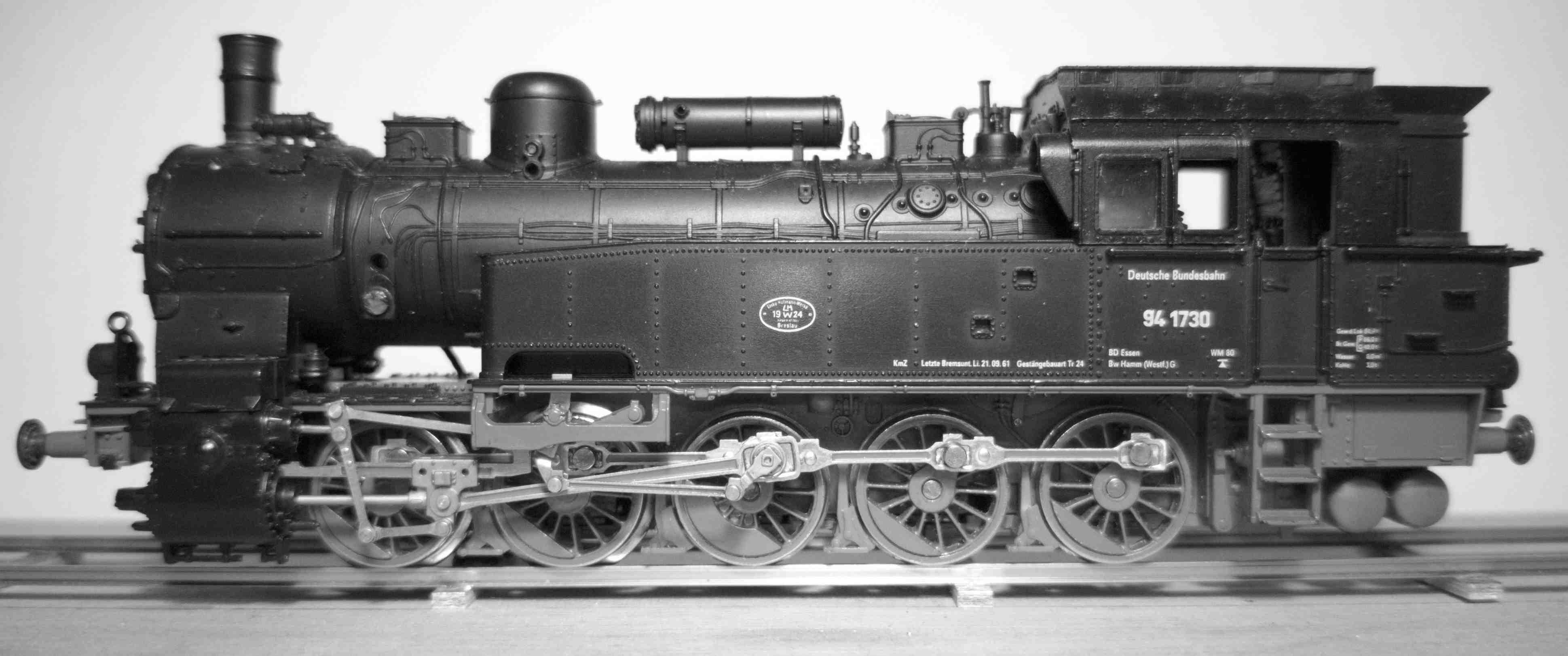
I have not had an empty workbench since I last posted something here. Here's something completely different in prototype, scale, the nature of the work and the type of model. This time the job is to improve the look of the wheels of a ready-to-run H0 loco. It's the Fleischmann ex-Prussian T16 tank loco from the 1970s or 1980s, bought in a rather battered condition for purposes of experimentation. The standard of fidelity and the workmanship Fleischmann achieved with these models were very good for their day, though of course expectations have risen since then. But having a solid basis suggests the models will be good candidates for some modification. In particular, reducing the huge flange depth.
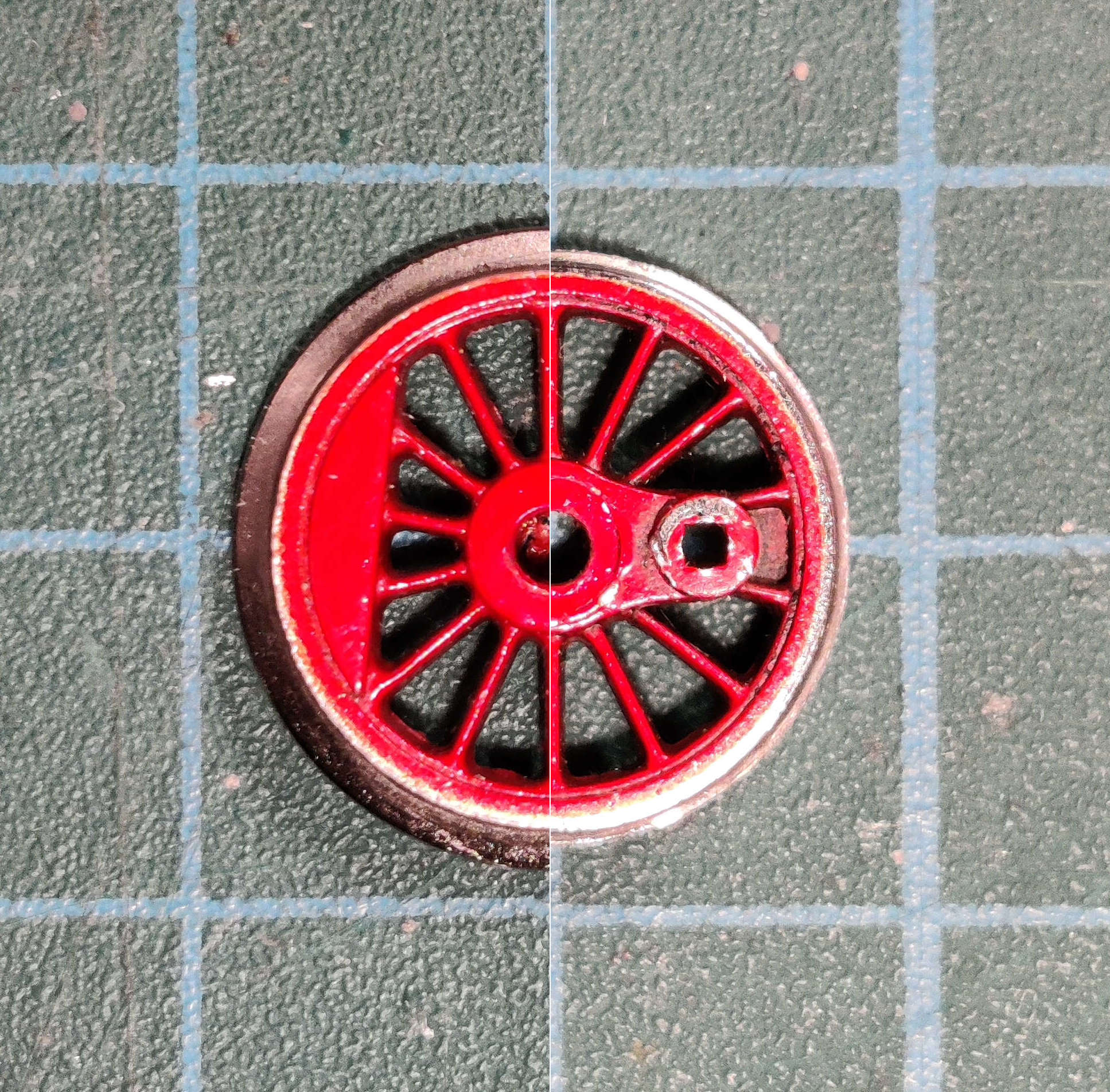
Here's a composite view to show the difference in flange height before and after. Judged on the shaping of the wheel boss, spokes and tyre rim this is a nice casting and I think that this adds a lot to the positive overall impression given by the model. Newer mass-market models in H0 scale (which probably have a common origin in Asia) tend not to have such nice looking wheels. It really helps that this is a single metal casting.
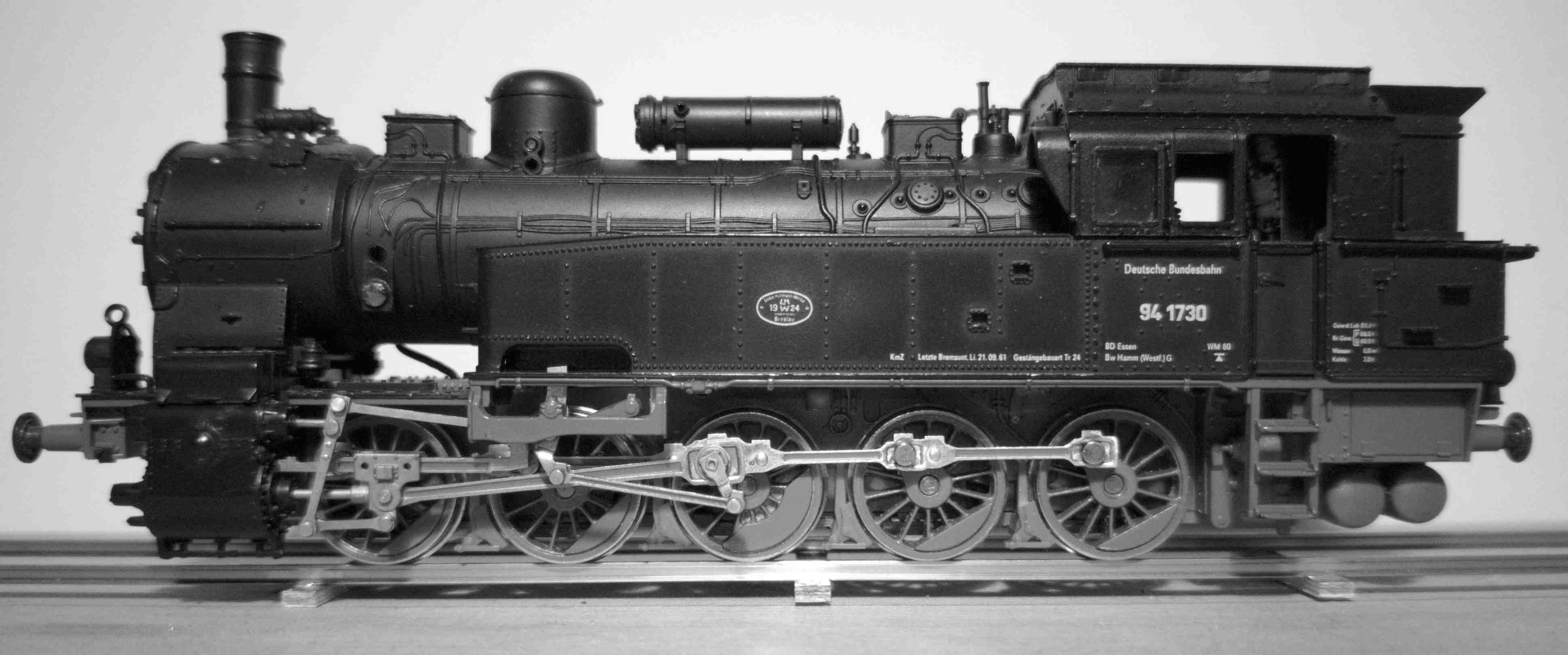
Here's the first trial, after I'd worked on the six rearmost wheels. The front two wheels are less easy to see, but the enormous flange still shows up clearly.
And here's the whole lot done.
Working on a lathe is still new territory for me and most jobs require trial and error. In this case I had a set of wheels from another loco to test my ideas. What worked best was to put each wheel face-first in a 15mm collet and then cut straight through the wheel back towards the chuck. I set the tool position to take off an amount that brings the flange height fairly close to the relevant NMRA RP-25 dimension (which is based on the full width of the tyre, not as manufactured but after thinning the wheel). The amount I removed from the flange height is about 0.7 mm, the original height being about 1.2 mm.
I haven't thinned the flange yet because I wanted to reassemble the whole lot and see whether it could cope with real trackwork first. I'd already added some washers to the axles, which had masses of sideplay (the most on the middle axle as expected). More adjustment is still needed now and I might fiddle with the front to back depth of the flanges on the centre drivers -- which would be replicating what was (usually?) done on prototype locos with lots of axles in a rigid frame.
The prototype locos had very closely spaced axles, Here is a prototype view of a similar loco, apparently missing as many parts as my model. Fleischmann's flanges meant that the wheelbase has to be overscale by about 4 mm, but RP-25 flanges on correctly scaled wheels would still not allow the correct wheelbase. The Fleischmann wheel diameter is 0.5mm underscale so there is a little leeway here. What I would like to do in the end is make new frames for the model and re-use these wheels. This would mean I could get rid of the 'pancake' motor and bring the wheelbase in closer to scale. As noted in my earlier posts this is another area where I have not yet got much experience, so taking time first to tweak the sideplay and find out how to minimise the chances of the loco ending up on the ballast seems to offer a sensible chance of progression. In the past two different aftermarket chassis for the model were available with full compensation and these are still sought after.
Leaving aside the details that were missing when I bought the loco, as well as the ones that I either pulled off deliberately or may have broken, it is not very difficult to pick out features such as the sketchy valve gear that are pretty crude. But if the model can 'take' the new wheels then that's an encouragement to re-detail because it lifts the overall impression so much. The later releases of this model have much more faithful valve gear, available as a spare part if necessary, and there is a cast metal front buffer beam available from a third party manufacturer to replace Fleischmann's one which has the buffers set the wrong distance apart. In my view this is one of those models that seems to look right somehow, a trick that doesn't seem always to correspond exactly with fidelity to the prototype, so I hope to give mine some more pushes in the right general direction.
Ben
Here's a composite view to show the difference in flange height before and after. Judged on the shaping of the wheel boss, spokes and tyre rim this is a nice casting and I think that this adds a lot to the positive overall impression given by the model. Newer mass-market models in H0 scale (which probably have a common origin in Asia) tend not to have such nice looking wheels. It really helps that this is a single metal casting.
Here's the first trial, after I'd worked on the six rearmost wheels. The front two wheels are less easy to see, but the enormous flange still shows up clearly.
And here's the whole lot done.
Working on a lathe is still new territory for me and most jobs require trial and error. In this case I had a set of wheels from another loco to test my ideas. What worked best was to put each wheel face-first in a 15mm collet and then cut straight through the wheel back towards the chuck. I set the tool position to take off an amount that brings the flange height fairly close to the relevant NMRA RP-25 dimension (which is based on the full width of the tyre, not as manufactured but after thinning the wheel). The amount I removed from the flange height is about 0.7 mm, the original height being about 1.2 mm.
I haven't thinned the flange yet because I wanted to reassemble the whole lot and see whether it could cope with real trackwork first. I'd already added some washers to the axles, which had masses of sideplay (the most on the middle axle as expected). More adjustment is still needed now and I might fiddle with the front to back depth of the flanges on the centre drivers -- which would be replicating what was (usually?) done on prototype locos with lots of axles in a rigid frame.
The prototype locos had very closely spaced axles, Here is a prototype view of a similar loco, apparently missing as many parts as my model. Fleischmann's flanges meant that the wheelbase has to be overscale by about 4 mm, but RP-25 flanges on correctly scaled wheels would still not allow the correct wheelbase. The Fleischmann wheel diameter is 0.5mm underscale so there is a little leeway here. What I would like to do in the end is make new frames for the model and re-use these wheels. This would mean I could get rid of the 'pancake' motor and bring the wheelbase in closer to scale. As noted in my earlier posts this is another area where I have not yet got much experience, so taking time first to tweak the sideplay and find out how to minimise the chances of the loco ending up on the ballast seems to offer a sensible chance of progression. In the past two different aftermarket chassis for the model were available with full compensation and these are still sought after.
Leaving aside the details that were missing when I bought the loco, as well as the ones that I either pulled off deliberately or may have broken, it is not very difficult to pick out features such as the sketchy valve gear that are pretty crude. But if the model can 'take' the new wheels then that's an encouragement to re-detail because it lifts the overall impression so much. The later releases of this model have much more faithful valve gear, available as a spare part if necessary, and there is a cast metal front buffer beam available from a third party manufacturer to replace Fleischmann's one which has the buffers set the wrong distance apart. In my view this is one of those models that seems to look right somehow, a trick that doesn't seem always to correspond exactly with fidelity to the prototype, so I hope to give mine some more pushes in the right general direction.
Ben
readingtype
Western Thunderer
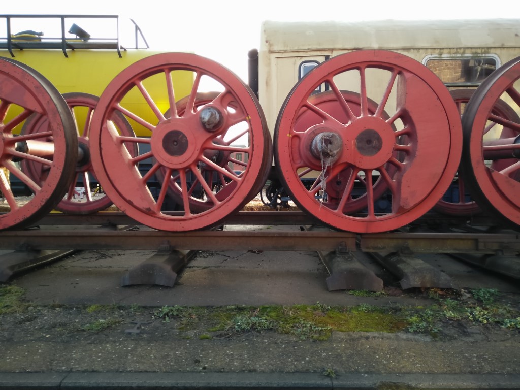
Here are prototype T16/BR 94.5 axles I photographed during a visit to Ilmenau, Thuringia, in 2018.
michael080
Western Thunderer
Hi Ben,
nice to see more prussian locos here around. I found this model under the christmas tree probably in 1978. It was state of the art at its time, but as you mention, the extended wheelbase has always been obvious. I still have it and I still like it. Märklin brought a T16 around 2015 that was pretty much on the same detail level as the '78 Fleischmann model. ESU had also a new design in the 2010s that had horrible wheels in my opinion.
You mention the third party chassis. The SB-Modellbau is only replacing the motor, the Graeler chassis is no longer available. As far as I know, only few were produced and they are worth their weight in gold.
If you want a nice looking T16, you may take a look at the Weinert kit.
Michael
readingtype
Western Thunderer
Thanks Michael! There was recently a thread over on Stummis Modellbahnforum covering the build of the Weinert kit. It has gone quiet now, but provided an insight into the kit design and the quality of the parts. When it comes to the frames, coupling rods and valve gear it's obvious that there is no comparison between that and Fleischmann's loco, but I suspect Herr Weinert did not have to worry about Christmas trees and what might be under them when creating his kits!If you want a nice looking T16, you may take a look at the Weinert kit.
Ben
readingtype
Western Thunderer
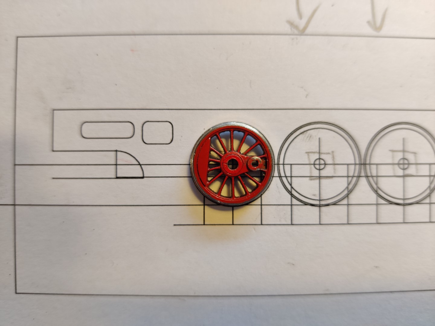
The trimmed Fleischmann wheels, because they are under scale, should fit on a scale wheelbase. Here's one sitting on a drawing at 1:87. The spacings come from the published dimensions and I'm making the drawing at 1:1 from the general arrangement drawing that can be bought from Harry's Model Shop.
To try to make the loco follow the track with its wheels rather than flanges, I've followed the prototype and made the first and last axles able to slide sideways as per Fleischmann but reduced the play on the second and fourth axles. I think I also need to reduce the back to back a little too (my gauge is probably a bit too 'finescale'). It's obvious why a fully compensated chassis such as the one Holger Gräler used to produce is desirable for any layout with a turnout on it! Fleishmann didn't alllow any up and down movement at all, beyond the slack in the bores for each axle.
Ben
readingtype
Western Thunderer
Wheels turn slowly.
I'm taking the extra thickness off the flanges now. The same amount comes off in this plane as off the height. Some less than excellent photos:
1. Flange after taking down the height

2. Flange after taking down the thickness

The thinning removes about 0.6mm from the thickness of the wheel, so with the back to back staying as it was the outer wheel faces will be 1.2mm closer and the tyres will be positioned differently on the rail heads. I did have it all straight in my head as to how this would help the loco to run better, but I suspect that was just the kind of endorphin I needed to persuade myself to pull all ten wheels off again. The only way to quarter the axles is on the loco and as I work away at this I will probably, as in the past, ponder the nature of the jig that Fleischmann's workers used and whether I could better spend my time trying to recreate it than fudging and twisting things about.
I'm taking the extra thickness off the flanges now. The same amount comes off in this plane as off the height. Some less than excellent photos:
1. Flange after taking down the height
2. Flange after taking down the thickness
The thinning removes about 0.6mm from the thickness of the wheel, so with the back to back staying as it was the outer wheel faces will be 1.2mm closer and the tyres will be positioned differently on the rail heads. I did have it all straight in my head as to how this would help the loco to run better, but I suspect that was just the kind of endorphin I needed to persuade myself to pull all ten wheels off again. The only way to quarter the axles is on the loco and as I work away at this I will probably, as in the past, ponder the nature of the jig that Fleischmann's workers used and whether I could better spend my time trying to recreate it than fudging and twisting things about.
Last edited:
readingtype
Western Thunderer
Far from a masterpiece but here are the wheels refitted. The thing zipped round the MRC test track earlier today staying firmly on the rails. The second and fourth axles have the least play so the loco tends to adopt a slightly tangential aspect on curves, but it stays on.
I think the reasoning I was struggling with earlier in the week about the back to back runs as follows. I have a 'finescale' 00 back to back gauge. I used it to set the axles before I had skimmed the wheels. This meant everything was extremely tight on the track, pretty much guaranteeing a derailment as flanges will start to climb the side of the rail almost as soon as they touch, and touching is likely with very little tyre width in between. Now the wheels are probably roughly up to the standard the gauge was made for, things will go better.

I think the reasoning I was struggling with earlier in the week about the back to back runs as follows. I have a 'finescale' 00 back to back gauge. I used it to set the axles before I had skimmed the wheels. This meant everything was extremely tight on the track, pretty much guaranteeing a derailment as flanges will start to climb the side of the rail almost as soon as they touch, and touching is likely with very little tyre width in between. Now the wheels are probably roughly up to the standard the gauge was made for, things will go better.
Last edited:
readingtype
Western Thunderer
To make much more difference to the loco, beyond cosmetics, the plan is to create new frames for the existing wheelsets. This drawing (work in progress) overlays a scaled drawing of the T16 frames made from the 'general arrangement drawings' onto measurements of the mazac/zamak Fleischmann chassis. The black lines are the measurements from the model. The longer wheelbase of the model is clear.

readingtype
Western Thunderer
My inspiration comes not least from the Teichmann chassis which was available from the mid-1990s. But I plan to take a more conventional 'British' approach with sheet brass frames and bearings, and without the (impressive) gear chain.
readingtype
Western Thunderer
Going back a long way to this post: following the comments that were made, I ordered suitable basic MJT hornblocks from the EM Gauge Society stores and they've been slumbering for some time now.
In a free moment about a fortnight ago, I assembled one of the guides as far as putting the tabs in the slots. Then I tried a few of the bearing blocks in the guide. The fit was more sticky than a sliding fit should be. I guess I need to touch all four sides of each bearing on some fine abrasive paper, as there's no logic in attempting to take thickness off the inside faces of the guides. Can anyone advise? The instruction sheet doesn't cover this -- and given how long these hornblocks have been in production I would guess tolerances and/or the specification may have moved around a little since it was written.
In a free moment about a fortnight ago, I assembled one of the guides as far as putting the tabs in the slots. Then I tried a few of the bearing blocks in the guide. The fit was more sticky than a sliding fit should be. I guess I need to touch all four sides of each bearing on some fine abrasive paper, as there's no logic in attempting to take thickness off the inside faces of the guides. Can anyone advise? The instruction sheet doesn't cover this -- and given how long these hornblocks have been in production I would guess tolerances and/or the specification may have moved around a little since it was written.
readingtype
Western Thunderer
Incidentally, my plan is to use the same hornblocks (with 2mm bore bearings) in my Fleischmann BR 94 frames project.
readingtype
Western Thunderer
The 1:76 scale Great Eastern S56 (J69/1) build I started a few years ago was halted for want of hornblocks during the pandemic (in fact, over three years ago: this turns out to have been long enough for Accurascale to get quite a long way with their RTR version). I did get the hornblocks in the end, and read the instructions, and did a dry run assembly, but there was a problem. I really don't like two-part epoxy resin glue, and that's what the instructions recommended to hold the two parts of each block together. The matter rested again, not that it had really stopped relaxing, until I built up a small set of things that all needed to be glued with the same glue. Last Friday I confidently cycled off to the DIY shop and returned much later with a flat back tyre and one of those epoxy dispensers that never disgorges the same amount from each of its two barrels. Having made what seemed to be a reasonable mix
I glued the U shape guides to the backing plates and left everything to set.
Today I put the frames and the hornblocks into my Poppy's frame assembly jig, spaced the axles out using the coupling rods, decided things looked good, and put a spot of solder on each block to tack it to the frames.
This did not go as wonderfully well as I would really like. I thought the spot of solder was the minimum needed, but capillary action absolutely held the hornblocks firmly in place. My intended tactic of remelting the joint and tweaking each block into exactly the right location was a failure, and I even succeeded in melting off the epoxy resin from one of them and so detaching the guide. This generated a smell even less pleasant than the stuff has before curing.
The blocks had a tendency to rotate around the axle when soldered, and it was this rotated position that I was hoping to correct when things went west. On reflection this seemed like a good moment to stop and take stock!
Ben
Last edited:
Paul Tomlinson
Western Thunderer
Ben, you might find life a bit easier by using single-piece hornblocks from either High Level (etched) or London Road Models (cast). Have a look at Kier Hardy's build of a High Level 03 which uses springs to stop the hornblocks rotating before they're soldered in.
readingtype
Western Thunderer
Much obliged Paul! I've seen this done in other photos -- and now I know why! I don't mind trying again with the blocks I have (and that's not just because I don't want to find yet another two-part kit I can't build ;-) but I definitely do not want to repeat what I did earlier today.Ben, you might find life a bit easier by using single-piece hornblocks from either High Level (etched) or London Road Models (cast). Have a look at Kier Hardy's build of a High Level 03 which uses springs to stop the hornblocks rotating before they're soldered in.
So the even pressure from those springs is enough to keep the blocks in position?
AJC
Western Thunderer
Sorry to hear of your misadventures with hornguides - I must admit that I was a bit surprised when epoxy came into the equation (this probably says something about my failure to read instructions as I've assembled a dozen or more of those MJT blocks and soldered them every time, probably having recycled the paper and card first... I must have looked at the diagrams but I've never knowingly read the words). I can see how this might make sense, but I can also well understand how what happened, happened: I've done the same with solder assembly if that makes you feel any better, so it's not a result of using epoxy per se.
Anyway, offering up hornguide assemblies is always nerve-wracking for me, but the protruding tabs that the MJT etch supplies offer a useful datum point for getting the sub assemblies in the right vertical position - the High Level design has something broadly similar. I can see that at least one of yours is off, and consequently sliding at an angle (probably the pair on the centre axle). Yes, I have done this, too. More than once.
Yes, the aim of the springs is to hold the the bearings in place by application of even pressure, assuming that there's space in the frame assembly. Aluminium hairgrips can also serve that purpose, and the various bits of plastic tube supplied with the Poppy's jig seem to work well, too.
So what I'd do is to unsolder, clean up and start again - assemble the hornguides with a higher temp' solder (it doesn't matter what, really) and fit with a spot of 145 degrees. I generally just take a slice off the wire and use a spot of paste flux to tack it before soldering it in properly.
Hope that helps,
Adam
Anyway, offering up hornguide assemblies is always nerve-wracking for me, but the protruding tabs that the MJT etch supplies offer a useful datum point for getting the sub assemblies in the right vertical position - the High Level design has something broadly similar. I can see that at least one of yours is off, and consequently sliding at an angle (probably the pair on the centre axle). Yes, I have done this, too. More than once.
So the even pressure from those springs is enough to keep the blocks in position?
Yes, the aim of the springs is to hold the the bearings in place by application of even pressure, assuming that there's space in the frame assembly. Aluminium hairgrips can also serve that purpose, and the various bits of plastic tube supplied with the Poppy's jig seem to work well, too.
So what I'd do is to unsolder, clean up and start again - assemble the hornguides with a higher temp' solder (it doesn't matter what, really) and fit with a spot of 145 degrees. I generally just take a slice off the wire and use a spot of paste flux to tack it before soldering it in properly.
Hope that helps,
Adam
Last edited: