7mm Manning Wardle Old Class i: a self-designed 'kit'

Ian@StEnochs

Western Thunderer
John,

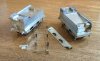
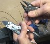
To stop the half round wire twisting it needs to be held very close to the bend and constantly flattened out. I have had some success holding the wire in smooth jaw parallel pliers and bending round a suitable sized drill shank held in the vice. Mine are Maun brand. A wide pair to hold the straight bit and a finer snipe jaws to gently easy the wire round the bend. Sub 1.5mm bends without annealing but anything bigger needs to be softened.


08D78567-7F9A-4368-9751-85962785404B.jpeg 706B4F68-21E1-4845-9E47-C73A4B294222.jpeg

68A5DCF5-7270-44C7-9931-863993BA8A9A.jpeg

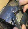
Another way of getting tight half round bends, cab beading etc, is to bend up some ordinary wire to the shape, solder the shaped wire onto a piece of plate and then file half away or mill it if you have a machine.

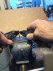
Soldering angles together before bending works well and you get a right and a left piece with one bending!

Ian.
 

Attachments

  • 72525086-8FF0-42DB-A8AD-01220E7F923D.jpeg
    72525086-8FF0-42DB-A8AD-01220E7F923D.jpeg
    262.3 KB · Views: 8
  • 4437377F-8F8E-4820-A352-D4DFF8AA6EA0.jpeg
    4437377F-8F8E-4820-A352-D4DFF8AA6EA0.jpeg
    183.5 KB · Views: 8
  • E69A1FBE-99F4-4ECD-AC6F-DB5C3E97071F.jpeg
    E69A1FBE-99F4-4ECD-AC6F-DB5C3E97071F.jpeg
    107.2 KB · Views: 9
  • 234DFD1D-8872-46C2-80FD-8B7A25C02613.jpeg
    234DFD1D-8872-46C2-80FD-8B7A25C02613.jpeg
    153 KB · Views: 9

John Baker

Western Thunderer
Having discussed different methods to forma lateral curve in half-round beading above, here's a quick comparison. The first image of the right hand side was formed by soldering 2 pieces of beading back to back to make a round wire. The curve was formed around a drill bit of suitable size, and the 2 pieces were separated, and soldered to the cab side.
In the second photo of the left hand side, I soldered the beading on whilst the cab side was in the flat, and then formed the curve. Whilst the net result is very similar, the second method I found considerably less fiddly, and much easier to clean up.

IMG_4507.jpg

IMG_4521.jpg
 

John Baker

Western Thunderer
Straight forwards construction of the smokebox, with a front, rear and base (with fixing nuts for attaching to the running plate), with a riveted wrapper around the outside. The castings for the smokebox door and chimney are solid, and so unusually for me, I decided to epoxy these in place rather than solder, as I feared the heat needed would make everything fall apart. The flare on the chimney needed a bit of altering - I'll do this on the CAD file before I get another set cast. It's still not perfect now, and will need a bit of filling.


And just staged for a quick photo to show the state of play so far. The boiler is a length of nickel silver tube.


Tank next......
 

John Baker

Western Thunderer
Here's the tank completed, ready for soldering to the boiler. I've added the handrail knobs and the injector fittings. On second thoughts, I'm not sure if it's an injector per-se, or if it's just a pipe junction into the tank. It is just a single pipe out of the tank, and I'm not sure if the early old class i's (which this is) had injectors or not. I just (blindly) followed the drawing! Answers on a postcard, and apologies for my lack of loco anatomy knowledge.....

IMG_4703.jpg.7a66fb364ccad9ecd4dcf3f9d4aa41e3.jpg

Whilst the tank filler seems to be correct when compared to the drawing I have, I think it looks too bulky/tall in comparison to the tank itself. I may well (try and) remove it and 3D print a replacement. So if anyone knows how to remove Devcon 2 ton epoxy (yes I know.....belt & braces etc.) without completely wrecking the thing, then let me know ;-)
 

AndyB

Western Thunderer
Isopropyl alcohol softens epoxy too.
I used this successfully recently to remove a buffer housing for which I'd put the buffer beam hole in the wrong place. (wasn't obvious with just the hole in the beam but definitely was with the buffer housings glued in!)
Andy
 

simond

Western Thunderer
I must be unlucky, I epoxied the ends into a tank wagon, aligned everything carefully, and secured it with elastic bands.

Mistake; it moved during the cure, and despite being immersed for days in acetone, I have not been able to recover the situation.

Maybe I’ll draw it in CAD and ask/pay someone with one of these fancy printers to print it for me. That would solve the issue of hundreds of stick-on rivets that will be required too.
 

John Baker

Western Thunderer
Several strips of brass later, I have something for the bunker flares that I am reasonably happy with and can reproduce on the etch with what should be minimal work after fitting. Looking at the photos, there's a bit more filling of joins with solder and then filing back needed. I thought it looked ok when I did it, albeit in the dodgy light of my spare room, but apparently not so!

Still, for my first bash at flaring, I'm reasonably pleased. I'm afraid it all needs a good clean up - the poor thing has been sat around for a while.....


John Baker

Western Thunderer
Been a while since my last post - a combination of work, illness, Christmas and a side project have slowed things down. I have added the springs, tank brackets, lubricator warming valve, boiler bands, clack valves and sandboxes, as well as remodelled the tank filler, which I printed. I realised I forgot to cast the sandbox filler caps, so printed these as well. Lots of little bits that weren't really worth a post individually. I'm currently (re)cutting the boards for the cab - I haven't much information about the cab interior, and a member on another forum pointed out that it's likely the boards would have run perpendicular to the frames. Here's the current, rather grubby state of play - I suspect there might not be much further progress over the next few days!

IMG_4886.JPG.0a0c82e6eafa0e3ecd8c6cd8589f3b8b.JPG


950834439_IMG_48883.jpg.40ded2cc44b7acf879d75a1eaf1d0ecf.jpg


Have a peaceful, hopefully model-filled Christmas!

John
 

John Baker

Western Thunderer
Absolutely superb John .
I love watching each step forward with this wonderful project!
Best Christmas wishes,
Neil.

Thanks Neil - each step forwards is a bit sporadic at the moment. Getting close to the point where I need to make it move under it's own power, hopefully with some waggly bits too.
 

John Baker

Western Thunderer
I keep telling myself I should give everything a good scrub and polish before posting photos...one day I will....before painting!
Since my last post, I have added the sandbox levers, draincock reach rods and the reverser reach rod.
Then, attention was turned towards the cab roof. The straps locate in a half etched recess, inside and out, and the spectacle frames were all soldered on. Having consulted the CAD drawing to work out where to form the bends, I nearly messed things up. Not only do I need a certain distance of roof from back to front, the front and back panels are at different heights. Needless to say, I put the bends in the wrong place. A bit of finger and thumb persuasion later, I managed to persuade it almost into the right place, although the front panel sits a bit too far towards the back of the firebox really, but nobody will know if you don't tell them. The whistle, brackets and stays were then added.
I'm not going to attach the roof to anything yet - I'll paint it first and worry about that later!

IMG_5028.jpg.6939cd6a41f3bab0f37687005c0c0893.jpg

IMG_5033.jpg.d0a507323b2ffce2006af7b963bbbf3c.jpg

IMG_5040.jpg.9789813c22e807168e9f5d407e31421e.jpg
 

John Baker

Western Thunderer
The gearbox I was making didn't quite work out - most of it worked well, until I got to the final spur gear on the axel - I needed to drill & ream this out to the correct bore. This sounds easy enough and in theory it should have been, but I don't have the equipment to hold the gear exactly perpendicular to the drill. Gripping it firmly enough whilst not damaging the teeth was another issue! It all led to a wobbly final spur gear, which bound everything up.

I'll keep working on populating the workshop with kit..... Onto the next solution to powering it. In a perfect world I'd get a nice ABC gearbox, but I can't afford one of these at the moment. A while ago, I bought a selection of N20 motor/gearbox combos from China. I designed a 'holder' to secure the gearbox at the correct distance from the axel, which was connected to the axel via some cheap 0.5 MOD bevel gears. The gearbox is either a 100 or 200 RPM version - not sure of the ratio, but it's suitably slow. The motor/gearbox/bevel gears/3D printed housing cost less than £5.

So far, so good. They seem very powerful for their size - I guess we'll see if it's strong enough to move everything when all 6 wheels, inside motion and two or 3 wagons are being pulled. Maybe by that time there'll be enough in the kitty for a 'proper' gearbox!


Finally, I gave the boiler assembly and cab roof a splash of etch primer, suitable thinned for a smooth finish.
IMG_5061.JPG.4cc2daf09008c47d8f070b1537658bc8.JPG
 
Top