The Heybridge Railway, 1889 to 1913

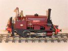
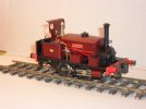
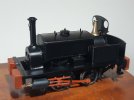
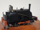
* model of 'Sankey' built by Allen (unpowered) *

Allen M

Western Thunderer
Hello Richard
I built one about 3 years ago as Sankey on the Edge Hill Railway (1 of the Colonel Stephens lines).
The loco as a whole was as the kits but buffers, normal & center dumb, and brakes where changed to suit.
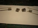
One point I would advise. The cylinders have two little tags on them which fit through holes on the frames for soldering (gluing) on. I drilled a third hole for a small screw, 10BA or may have been 8BA. This was fixed to the casting before the whole assembly was built. Jus be careful the dead does not catch the piston rod. Everything can now be built & painted the cylinder assemblies attached with (bit of a fiddle) nuts.
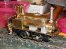
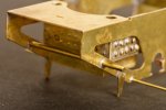
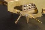
49 - First fit side-front.JPG63 - Side view posed.JPG64 - Three quarter view posed.JPG

Hope this is of help

Regards
Allen
 

Richard Gawler

Western Thunderer
Allen, these photos are going to help me a lot, they explain details which are not so obvious from the instructions and the photograph on the box. The screws and nuts to hold the cylinders sound sensible, I would not have thought of this on my own.

I have some photos of ‘Sankey’ and it seems like a good example to work from because it is the right age (built 1888) and has less rivet detail than some of the others.

Did you fit the motor entirely inside the firebox? I have a motor and ‘multibox’ gearbox from Branchlines, recommended by the proprietor and by Slater's. Of course, a photo of the other side of your loco or the chassis would be much appreciated too :)
 

Herb Garden

Western Thunderer
View attachment 194983
I bought the kit for the MW class F in November last year, when I felt the Y14 was going to work out okay. I am hoping this kit is a sensible progression for me. It is my first loco with outside cylinders, first with suspension, first with sprung wire pickups, and first with a two-stage gearbox.

It is also my first brass kit for any coach, wagon or loco not created by Connoisseur Models; and so my first without Jim’s marvellous instructions and a first without the unwritten but frequently re-quoted words, “they go together”. Slater’s have few loco kits on their web site but this one has the year 1985 on its etches, and even the name of the designer too. Their wagon kits are good, so I can be optimistic.

View attachment 194984
There are four etches for the body from 0.4 mm brass, one for the chassis from 0.5 mm brass and one for the side rods from steel. There are alternate parts for different cabs and spectacle plates and one of the etches is devoted to an enclosed cab. The parts are numbered on the etches, which looks good, but I see numbers 1 to 6 at least are used twice, perhaps not so good.

View attachment 194986
The detail castings are of a very good standard so if they fit I should be able to build a good-looking model. I am guessing the metals here are pewter as well as white metal and brass. Nice touches include turned steel buffer heads (though I might take these for my GER van) and plenty of spare half-etched holes to practise embossing rivets. The boiler has been machined as a brass cylinder and will need work to open up space for the motor.

I have stumbled upon an essay on these locos in MRJ number 6, and gone on to find their magazine project to build the loco from scratch in 4 mm scale. I could never cope with the intricacy in the smaller scale, but in 7 mm I think I have a chance.

View attachment 194987
The bench is rarely anywhere near this tidy!

I have made a modest start on the frames but the current September heatwave makes it far too hot to do much more. Hopefully an update next weekend.
So I have one of the set of parts for the 4mm MRJ version of which you speak... you might have inspired me to get them out and start building...

Are you going for a purely light railway machine or the GERs own #200?
 

Richard Gawler

Western Thunderer
I didn't know the GER had one!

The idea is to build this as a light railway machine. It will be the property of Bentall's foundry but lent to the Heybridge Railway when their own 'Blackwater' is having maintenenance. It might become the shunter at Heybridge Basin after the arrival of Nellie the crane tank.
 

Richard Gawler

Western Thunderer
I have read, no. 200 spent its life at Stratford. For me, it will be best to choose a more camera-shy loco. Perhaps works number 1050 of 1888, built four months before WT no.7 'Massey'. 1050 was supplied new to T A Walker, and conveniently exported to South America.

(from the Locomotive Works List for MW compiled by F W Mabbott, published 1982)
 

Allen M

Western Thunderer
Hi Richard
A bit more info with photos. First I don't have one of the other side.
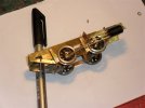
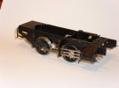
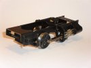
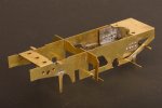
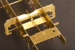
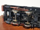
There is no motor/GB as it was built to be a static exhibit in the Colonel Stephens Museum Tenterden K&ESR. From memory the motor/GB you have should fit OK but as I built it in 2009 without not 100% sure. If my memory is correct the the rear axle is fixed with the motor and the front axle rocks with a center bearing. 10 Connecting rod & brake block front.JPG9 - Connecting rod & brake blocks rear.JPG4 - The cylinder bits.JPG7 - Cylinder assembly completed.JPG45 - Chassis left.JPG43 - Chassie front right.JPG44 - Chassis rear right.JPG

Hope these are of help.

Regards
Allen
 

Richard Gawler

Western Thunderer
Allen they are of a great help and they will help anyone tackling this kit for the first time.

I was going to the Colonel Stephens Museum last Tuesday, abandoned the idea because of other commitments and now I will be on the look out for your loco as well as the full-size exhibits. I will take a photo of the other side if I can see it :)
 

magmouse

Active Member
Richard - you also might find this a useful resource, with both the background to the company and loco development, and lost of pictures of the different Manning Wardle types:

Locomotive Builders of Leeds: The history of E. B. Wilson and Manning Wardle.
Author: Mark Smithers.
Publisher: Pen & Sword.
Hardback. 199pp. 22cm by 28cm.


Nick.
 

Richard Gawler

Western Thunderer
I bought the book by Mark Smithers after I bought 'Blackwater', I can only admire his attention to detail because I have read only the parts relating to the class K and the class F. I am not a very good reader nowadays, I think the Internet has trained me to look for only details of immediate value.

@Allen M has sent me some scans of an article on the class F owned by the Southern Railway, written by Colin Binnie and published in 'Model Railways' in 1972. This article is also online on a web site dedicated to Colin's work:
Sothern Railway Loco` 225S by Colin Binnie.

I love the roof, I want one of these.
 
Last edited:

Rob R

Western Thunderer
I have read, no. 200 spent its life at Stratford. For me, it will be best to choose a more camera-shy loco. Perhaps works number 1050 of 1888, built four months before WT no.7 'Massey'. 1050 was supplied new to T A Walker, and conveniently exported to South America.

(from the Locomotive Works List for MW compiled by F W Mabbott, published 1982)
Richard,
GER 200 (AKA Works A, The Chairman) was a MW H class, a bit bigger than the Slaters F class (3ft wheels etc).
Rob
 

Richard Gawler

Western Thunderer
GER number 200 can still give me something useful - its designation. The loco received its designation "Works A" in 1894 (when it arrived at Stratford) and this is contemporaneous with the imaginary arrival of my class F at the foundry of E H Bentall. I shall call it "Heybridge A".
 

Richard Gawler

Western Thunderer
I have made a modest start on the frames but the current September heatwave makes it far too hot to do much more. Hopefully an update next weekend.

I have started the build by soldering parts together rather than deciding precisely which prototype I want to build. This probably sounds a bit reckless but I will at least try to drill the holes needed for extra fittings while the parts are still flat on their frets.

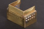
1. Lower Firebox and Ashpan

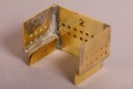
The lower firebox is supposed to be a simple fold-up assembly but mine ended up too wide to fit between the frames. It also ended up as a terrible mess while trying to make it fit, no photos of this.

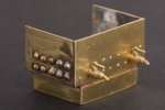
Eventually I realised the sensible approach was to cut both sides away from the back (these were all one piece) and assemble the three parts with the sides in front of the back and not outside it. I had ruined one side trying to flatten out my embossed “stays” (trying to make space) so I made a new side from scrap brass and drilled holes in both sides to accept pins to represent the stays.

DSC_4260.jpeg
This made a firebox most of a millimetre narrower and an easy fit between the frames. I have forgotten which is the new side.

DSC_4258.jpeg
There is a fair amount of solder inside holding this together. I learnt a lot when I ruined the smokebox of the Y14.

DSC_4288.jpeg
Curiously, the sides of the ash pan were much easier to place onto the narrower firebox. There was next to no fitting involved.

My stays are thin brass pins. I sorted through them to find some with a consistent size of head. They are a bit chunky but if I end up with different sizes of lumps on the model for stays, rivets and bolt heads then I think this will look better.

I imagine the drain cocks on the prototypes were of brass and thus not painted, so I have put two brass tubes into the back so I can glue in the drain cocks after painting.

DSC_4292.jpeg
The drain cocks are a light sliding fit, just enough room for some glue. One of them is missing already; it flew over the workbench and out of sight. Best stay with hand tools for fettling small parts. I think these castings are superb.

So . . . the kit provides five parts to build the lower part of the firebox and the ashpan, and I have managed to use twenty-nine (arguably, thirty) for mine. So far so good :)
 
Last edited:

Richard Gawler

Western Thunderer
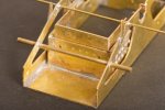
2. Frames and Attachments for Brakes

DSC_4333.jpeg
I could find an argument in favour of making the lower firebox a bolt-on assembly but I think I would find the screws a terrible fiddle, and so the speed and simplicity of solder have won the day.

DSC_4344.jpeg
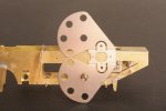
The design of the kit leaves the bearings for the rear axle free to rotate, and I have added lengths of 1 mm square bar to stop the bearings wearing the frames.

I left the cusp on the retaining brackets because they seem so small and fragile. To be honest, I can only see it in enlargements like this.

DSC_4338.jpeg
The kit provides a length of 1.5 mm wire to make the transverse rod for the brake operating mechanism. I fitted this rod without reading very far ahead in the instructions and it is far too fat to let me attach the brake operating levers.

DSC_4293.jpeg
I have used two 12BA washers to build up a boss to attach the first lever.

DSC_4304.jpeg
I don’t yet know the lateral position for these levers hence the Blu Tack for the photo.

DSC_4320.jpeg
The wheelbase of this loco is much the same as the track gauge. If it won’t go round a curve then it must be a right angle :)
 
Last edited:

Richard Gawler

Western Thunderer
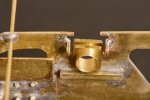
3. Front Suspension

DSC_4351.jpeg
This is the front axle with its rocking suspension bracket. I don't know whether this bracket is handed but I have given it a pair of centre punch marks so it can always go in the same way round.

DSC_4350.jpeg
For the record, I have not removed the cusp from the slots for the front wheel bearings because the bearings already slide very easily. Time will tell whether I still need to do this, but the rocking mechanism is working sweetly.

If I use piano wire instead of brass I will get some up/down springing as well as rocking from side to side.

The instructions for the kit are leading me towards setting up the cylinders next but I think it will be wise to investigate the motor and gearbox first. I have no idea how they will fit into the model, or even if they will fit at all.
 
Last edited:

Richard Gawler

Western Thunderer
DSC_4353.jpeg
I have a Branchlines Multibox gearbox (53:1 total) and a Mashima 12 volt, 14 x 20 mm flat can motor.

This combination will fit if I put the rear axle through the worm gear and discard the second stage, and this will give me 40:1. The motor will (I think) sit vertically inside the firebox. (If I use the complete gearbox, the motor will be taller than the firebox).

The design of the power train is going to be an iterative process:

(1) The loco would be marvellous with radio control, so I need to build the saddle tank to get an idea of how much space I have for the batteries and electronics. There isn't much room anywhere else.

(2) The chosen control system affects the ideal specification of the motor. I might want a 6V motor if I go for r/c, or maybe 6 volts into the 12V motor with 40:1 will give me enough speed - I don't know yet.

The main limitation is, I want to cut the frame of the gearbox before I fold it up. This could ruin the gearbox or turn out to be just right.
 
Last edited:
Top