LNWR Precedent

NickB

Western Thunderer
The firebox is the usual wrapper around a skeleton, and the boiler is simply a rolled cylinder.

Firebox skeleton.png

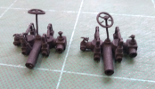
Then I did a trial assembly to make sure everything fits. The dome, safety valves and backhead are 3D prints.

Boiler and firebox.png

Here's the backhead in detail. It took quite a long time to draw because of the complexity, but it was worth the effort. I'm sure I saved myself a lot of time. Actually I had to carve bits off the bottom to get it to fit. It was just a bit too tight due to the stackup of tolerances (a posh way of saying that I got the boiler just slightly too long). In future I will try to allow for things like that when drawing them. Incidentally, there is some wierd camera lens distortion in that photo - the boiler fittings are actually in a line.

Backhead.png

Another interference point is that the boiler makes contact with the leading drivers because the G3 back to back dimension is smaller than scale. I'll have to cut out a clearance for that, which won't be visible behind the splashers.

Nick
 

NickB

Western Thunderer
Not much time in the workshop recently, what with other things (newsletters and shows, and Real Life) getting in the way. However, I've recently been continuing the bodywork with the rear splashers, which have a curved corner and then merge with the firebox.

Rear splasher.png

The tape is holding it temporarily in position. I'm not ready to solder it up, but I have to check the fit to the firebox and the fit of other cab parts to it. If you are hoping I can reveal some clever CAD-based method to make the curve where it meets the firebox, I'm going to disappoint you. The trouble is that anything I make that is folded or curved never comes out exactly to the drawing, and that applies here to both the splasher and the firebox. In CAD I can define the curved end of the splasher to the n'th decimal place, but in metal it never quite fits. Instead it required patient cutting and filing by hand until the gap is small enough to be able to solder it up – in fact, the traditional way.

The other problem was the arm rest on the top of the splasher. For some unaccountable reason I persuaded myself to solder the splasher side to an oversize piece of material and cut it to the correct profile. Not clever. It is really difficult to get the saw in close and still control it, so it goes wandering. After messing up the first two attempts, I did the sensible thing which was to cut it out first then solder it. The cutting was done on the milling machine with a rotary table to make the round end where the handrail fits, and after that it just needed the top edges rounding and polishing.

Arm rest.png

Nick
 

Mikemill

Western Thunderer
Nick

One way I have found to tackle boilers and firebox to fit over splashers is to make dummies. Draw out the development in CAD print it and use the print as a template to cut out the shape in styrene, then offer up to the splashers and note where adjustments may be needed, and repeat the exercise until you have a good fit.

However, there is always a bit of fettling needed.

Mike
P1030203.JPG
 

NickB

Western Thunderer
Splashers.png

I was peering under the footplate for some reason or other, and realised that the low angle could give an unusual and striking photograph. Since the sun was shining I took it out into the garden to make best use of the natural light. I don't have a garden railway, it is just perched on a suitable timber.

Both sets of splashers are done. A few details to add to the footplate then on with the cab.

Nick
 

NickB

Western Thunderer
The cab structure is mostly complete. The roof is the only outstanding part and that will be removable in order to access the interior and backhead. Like all platework, it is sawing, filing and soldering and there isn't much more to be said about it. People have asked about the sharp corners. The trick is to make one side very slightly (fraction of a millimetre) over-length, run a fillet of solder into the inside corner so formed, and file the excess away.

Cab exterior.jpg

Cab interior.jpg

Now that the nights are drawing in I'm less enthusiatic about heading to the workshop in the evening, so I've been drawing the backhead fittings. I haven't drawn all the pipework because that will be done using copper or brass wire, bent and cut to fit. The fittings will mostly be 3D printed in nylon or, where the finish is brass, cast from 3D printed masters. The casting is a lot more expensive, but fortunately the LNWR didn't go in for "bling" as much as some railways and were happy to paint rather than polish a lot of parts.

Cab fittings drawing.jpg

Nick
 

NickB

Western Thunderer
Santa (cleverly disguised as a delivery driver) came early this year. Let's see what is in the stocking ...

First up, brass castings of several backhead fittings.

Brass castings 1.png

Brass castings 2.png

These were done by the hybrid process: a wax pattern was made by 3D printing from my solid model, and that was used to make an investment casting in brass. It saves me having to make a pattern, and the casting quality is quite good enough and needs little in the way of finishing from me. I put all the parts on a sprue. Because of the nature of the casting process, that made a big difference to the cost over casting each part separately. However, the per-unit cost of casting is quite high for one-offs and to take advantage of the price breaks I had four sets made. That's one for this project, one for a future project still in the thinking about stage, and, er, two extra. Maybe there is someone out there also building an LNWR prototype?

Next a collection of parts 3D printed in SLS nylon.

PA12 fittings.png

Hmm, a bit of a mixed bag here. The little fittings - fixing brackets, elbows, tees - are nice. The reverser is okay but missing the handle on the outer rim of the handwheel (a bit of wire will fix that). Close up, the finish is a bit rough but I can smooth that down.

Reverser.png

The steam turret is supposed to have three handwheels.

Steam turret.png

The centre one is broken and the smaller outer wheels just haven't come out. Clearly the spokes are too thin for the printing process. In the past suppliers have warned about this sort of thing when I submit the file, but I guess they didn't do that check this time. I will take it up with them, but most likely I won't get anything more than a refund on these parts. Apart from the handwheels they are okay, so either I'll get the handwheels cast in brass and end up with a lot of extra ones, or I'll have to machine up the few I need. I will think about that over the turkey and pud.

The injector controls also have handwheels. In one case here one wheel is broken, but the other is okay and there are enough spare for what I want. When ordering 3D prints of small components, I often get considerably more than I have asked for at no extra charge. Mavbe that's how their automated process works. Whatever, more and more surplus fittings are accumulating in my workshop drawers.

Injector control.png

In the meantime I have also been machining some fittings that for various reasons weren't feasible or economic to print, or I just fancied making them the traditional ways. Here are the spectacle frames, gauges, whistles and safety loops. And there are more to come.

Machined fittings.png

In the detailing phase, I spend some time going over the drawings and photos, making a list of all the parts to do. That way things don't get forgotten, but it also gives me a sense of achievement as I tick each one off the list as I do it.

Nick
 

Attachments

  • Steam turret.png
    Steam turret.png
    320.4 KB · Views: 4

Ian_T

Western Thunderer
Well I hope to see the finished engine "in the flesh" one day Nick - amazing what is possible these days

IanT
 

NickB

Western Thunderer
I've started adding parts to the backhead.

Backhead assembly.png

This is where the photos of the cab interior of the preserved loco are really helpful because with all the pipework it becomes a 3D jigsaw so I am starting at the back and working forward. Once I've populated the backhead as far as possible, it goes into the cab and then the fun really starts.

Nick
 

Mike W

Western Thunderer
Here's my real regulator quadrant for comparison. Very impressive Nick! I particularly like the split (or whatever the technical word for it is) in the handle to allow it to grip the bar - never seen that modeled before.
Regulator 5.JPG
Mike
 

Jon Nazareth

Western Thunderer
Back to the loco. Most electrically powered locos, as far as I know, are built using a separate chassis and body, the body removing to get at the works. That's not going to work here because of the way the leading wheel spring is attached. The hangers are bolted to the frames to take the load, but the front hanger has to pierce the smokebox wrapper.

View attachment 187298

That means if you bolt the hangers to the frames, you can't get the smokebox off, but with the smokebox and boiler in place it is all but impossible to remove the spring. Incidentaly, on the real thing lead sheet was forced into the space between the hanger and the wrapper to preserve the smokebox vacuum. It all sounds like a bit of a bodge. Couldn't they come up with a better idea? Clearly, DFMA (Design for Manufacture and Assembly) hadn't been invented in Victorian times.

My answer is to attach the smokebox permanently to the frames. The boiler is part of the body assembly, and bayonets into the back of the smokebox. To remove the body, release the screws which will be under the cab, slide the body backwards about a millimetre, and lift it off vertically. It will work because there are only two external pipes connecting the boiler and the smokebox and it's easy enough to release them for dismantling.

The smokebox skeleton is a straight forward bit of sawing, filing, and turning.

View attachment 187300

Thw wrapper has two rows of rivets at front and rear. I decided to press them rather than add them separately and solder them, partly because I couldn't find any rivets of the right size, but mainly because I didn't fancy drilling so many tiny holes.

When I made my rivetting tool, many years ago, I designed it so that it could be clamped to the bed of my Sherline lathe. The work is clamped to the cross slide and moving the saddle and cross slide gives nice uniform rows of rivets in both directions. Here is the first row

View attachment 187301

and here is the second row, positioned by cranking the x-axis the correct amount and maintaining the same spacing on the cross slide.

View attachment 187302

I prefer doing it that way than relying on the anvil diameter to space the rivets. It works better for me but I know that the late, great Beeson and Reynalds both used the anvil edges, and who am I to argue?

Nick
Nick
Could you tell me please, how thick is the sheet for this wrapper. I've been trying to make up some tender sides out of .010" sheet nickel and I'm experiencing terrible distortion particularly at the edges.

Jon
 

NickB

Western Thunderer
I blame Bill Finch. If he hadn't published a book full of dimensioned sketches of the preserved loco, there are details I would never know existed, let alone model. And if I didn't get so distracted, it would be nearer finished. So, on the side of the cab we now have the staff carrier and the boiler certificate holder. Who knew?

Cab details.png

Nick
 

NickB

Western Thunderer
Jon,

The smokebox wrapper is 0.5mm (0.020"). Distortion is a problem that gets worse with thinner material. I find that is the thickest sheet on which I can impress rivets (without pre-drilling) and roll with my home made rolling bars. If an edge is visible (e.g. a footplate edge) and I can't disguise the thickness I will go down in size or taper the edge by filing the bottom surface.

Nick
 

Jon Nazareth

Western Thunderer
Jon,

The smokebox wrapper is 0.5mm (0.020"). Distortion is a problem that gets worse with thinner material. I find that is the thickest sheet on which I can impress rivets (without pre-drilling) and roll with my home made rolling bars. If an edge is visible (e.g. a footplate edge) and I can't disguise the thickness I will go down in size or taper the edge by filing the bottom surface.

Nick
Nick
Thanks for that. I’ll try again and see how I get on. I did reduce the pressure which in turn reduced the size of the impression but still the sheet distorted.

Jon
 

NickB

Western Thunderer
I wasn't happy with the print of the steam turret and I was prepared to replace the handwheels, but discovered that I'd made a mistake in the solid model so decided to do the whole thing again. This time I thickened up the spokes and lever arms in the hope of makng the print more reliable, and I got the print made elsewhere by an individual recommended to me by Mike Palmer (thanks, Mike).

Steam turret v2.png

It's done in a softer plastic but it carries no load so that should not matter. The quality is pretty good, though the spokes, particularly on the smaller wheels, now look a bit heavy. I will try to improve the appearance with a bit of gentle scraping with a sharp knife.

Nick
 
Top