USATC S100

spikey faz

Western Thunderer
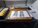
While I wait for some paint to dry on my last project (LSWR Crane Loco) I decided to dig this kit out.
20240128_160538.jpg


I bought this about the same time that Minerva announced their intention to produce an O-Scale rtr model!

If I manage to get going with this project I'll need to decide whether to model one of the Southampton based ones, or go for one of the overseas based versions.

I'm hoping that by starting this thread it'll 'encourage' me not to jack it in. Watch this space! :))

Mike
 

Paul Tomlinson

Western Thunderer
Mike, Good luck. You've seen the completed ones owned by Ian Metcalfe and Yorkshire Dave. A quirky and interesting loco. I came across this chap the other day on the G0G Traders List, who sells v.nice RTR models - there's a few variants which might be interesting to you...


spikey faz

Western Thunderer
Thanks Paul. :thumbs:

The oil-fired one appeals to me. :eek:

I've just been comparing the chassis etches to some scale plans. Looks promising although straight away I can see the pivot for the brake actuating arm appears to be in the wrong place.
20240128_163342.jpg

Mike
 

Yorkshire Dave

Western Thunderer
If I manage to get going with this project I'll need to decide whether to model one of the Southampton based ones, or go for one of the overseas based versions.

I'm hoping that by starting this thread it'll 'encourage' me not to jack it in. Watch this space! :))

No fear on the latter - I'll certainly be watching having built one myself. :)

However from my experience there are some things to watch out for - of which a few I didn't find out until part way through the build and subsequently corrected. There are other areas I modified especially around the cab as some parts of the etchings I felt were too flimsy.

I'll dig my model and some photos I took during the build for reference if of any use.

The main issue is the chassis is too long which I didn't find out until I had the chassis built. In the end I cut a buffer beam width section off the front of the chassis to give the loco the correct appearence. If I was doing this again I would take a half buffer beam width section off both the front and rear of the chassis

USATC S100 1.jpg

When I was building mine years ago the ex-SR/BR(S) S100 was still at Oakworth and I went there to take some photos - especially around the brake levers under the cab - I can also upload these if of any use.
 

spikey faz

Western Thunderer
No fear on the latter - I'll certainly be watching having built one myself. :)

However from my experience there are some things to watch out for - of which a few I didn't find out until part way through the build and subsequently corrected. There are other areas I modified especially around the cab as some parts of the etchings I felt were too flimsy.

I'll dig my model and some photos I took during the build for reference if of any use.

The main issue is the chassis is too long which I didn't find out until I had the chassis built. In the end I cut a buffer beam width section off the front of the chassis to give the loco the correct appearence. If I was doing this again I would take a half buffer beam width section off both the front and rear of the chassis

View attachment 207789

When I was building mine years ago the ex-SR/BR(S) S100 was still at Oakworth and I went there to take some photos - especially around the brake levers under the cab - I can also upload these if of any use.
Any pictures of your build and the prototype will be gratefully received. :thumbs:

Interesting what you say about the chassis length. I'll keep an eye that. I expect it to be an entertaining build!

Cheers
Mike
 

spikey faz

Western Thunderer
I've made a start on the frames. 4 x etchings: 2 per side.
20240129_190751.jpg


I've already hacked off the brake pivots.

There are some holes provided for tubular crossmembers, but I can't seem to find the crossmembers in the box. Unless the prototype was fitted with these I'm inclined to fill the holes on and revert to conventional crossmembers.

Probably going for springing on all 3 axles using Slaters components. I'm also thinking of using one of the Slaters motor/gearbox combinations.

I suspect I'll have to build most of the bodywork first before finalising the chassis construction as I want to make sure everything fits properly.

Mike
 

Pencarrow

Western Thunderer
I've made a start on the frames. 4 x etchings: 2 per side.
View attachment 207881


I've already hacked off the brake pivots.

There are some holes provided for tubular crossmembers, but I can't seem to find the crossmembers in the box. Unless the prototype was fitted with these I'm inclined to fill the holes on and revert to conventional crossmembers.

Probably going for springing on all 3 axles using Slaters components. I'm also thinking of using one of the Slaters motor/gearbox combinations.

I suspect I'll have to build most of the bodywork first before finalising the chassis construction as I want to make sure everything fits properly.

Mike

Gosh, not much meat on those frames is there!?
 

Yorkshire Dave

Western Thunderer
Hi Mike

Here's five photos of the chassis taken when I was building mine - which I trust may be of use.

I used the old Slater's hornblocks and arranged mine for split axle pick up. One thing you'll have to do with the coupling rods is beef up the rear sections as they were heavier on the prototype. This is evident from my photos.

The first three are in the early stages.
DSC_0500.jpg
DSC_0502.jpgDSC_0505.jpg

The next two are later in the build. I arranged for the steam chest pipes to be fixed to the cylinders as in my view makes the join next to the smokebox less obvious.

DSC_0629.jpg

DSC_0630.jpg

DSC_0632.jpg
 
Last edited:

Brian McKenzie

Western Thunderer
By WW2, were bar frames for these locos still being assembled from individual pieces, forged or welded together?
Where joined, they have very large radius fillets on the insides of the frame apertures. Would the vertical bars for such an assembly be shaped to include those fillets beforehand?

When North British Locomotive Company constructed bar-frame locos for New Zealand in the 1950s, they were cut out from thick slabs of 'Ducol' steel.

'Over the ditch' in Australia, I had a very good look at their famous 4-6-2 loco #3801, when it was in pieces during restoration. It's cast fame is a magnificent piece of work, incorporating not only cylinders, but parts such as brake hanger mounts, air reservoir and WHB pump bracket etc all cast in a single piece.

Air reservoir shown here:
NSWGR #3801 at Chullora_air reservoir in view_1083a.jpg
 

spikey faz

Western Thunderer
Hi Mike

Here's five photos of the chassis taken when I was building mine - which I trust may be of use.

I used the old Slater's hornblocks and arranged mine for split axle pick up. One thing you'll have to do with the coupling rods is beef up the rear sections as they were heavier on the prototype. This is evident from my photos.

The first three are in the early stages.
View attachment 207886
View attachment 207887View attachment 207888

The next two are later in the build. I arranged for the steam chest pipes to be fixed to the cylinders as in my view makes the join next to the smokebox less obvious.

View attachment 207889

View attachment 207890

View attachment 207891
These are really helpful. Thank you. :thumbs:

You've set the bar high with your model. I can see I've possibly got a fair bit of work to do to get this model how I want it.

Mike
 

spikey faz

Western Thunderer
Had some spare time on my hands today, and as Mrs Faz was working I decided to make a start on the cab. I'm looking to get the basic bodywork together, then I can check where I need to shorten the chassis.
20240130_093405.jpg20240130_105757.jpg20240130_105829.jpg20240130_110416.jpg20240130_153311.jpg

Some of the parts are displaying evidence of what I assume is over-etching and this has resulted in some parts becoming a bit weak, hence the masking tape holding things together.

Mike
 

Yorkshire Dave

Western Thunderer
Yes, there are some very weak areas - especially around the top of the cab door and windows.

These show some of the modifications I made around the cab and roof during the building of mine - apologies for my workmanship - my kit building skills are not up the the stratospheric levels as some WT members....:oops:

Around the cab I cut my roof into three sections. As my model is going to be no. 64 (s64) between June 1947 and January 1948 (during which she retained some US fittings) I also deepened the right hand rear window (as seen from the rear). This window size varied depending on the loco.

DSCF5634.jpg

Inside the cab I soldered brass wire to add some strength. The lip on the cab was bent back - very roughly looking at this now :). The outer parts I cut off the roof then formed and soldered to the cab.

DSCF5636.jpg

Treatment of the gutters

DSCF5639.jpg

As seen on the centre section of the roof.

DSCF5637.jpg

And the rebate/lip created by the roof gutters.

DSCF5638.jpg

I didn't like the roof ventilator casting so I made a new one from scrap brass etch and brass wire.

DSCF5639a.jpg
 

spikey faz

Western Thunderer
Yes, there are some very weak areas - especially around the top of the cab door and windows.

These show some of the modifications I made around the cab and roof during the building of mine - apologies for my workmanship - my kit building skills are not up the the stratospheric levels as some WT members....:oops:

Around the cab I cut my roof into three sections. As my model is going to be no. 64 (s64) between June 1947 and January 1948 (during which she retained some US fittings) I also deepened the right hand rear window (as seen from the rear). This window size varied depending on the loco.

View attachment 207999

Inside the cab I soldered brass wire to add some strength. The lip on the cab was bent back - very roughly looking at this now :). The outer parts I cut off the roof then formed and soldered to the cab.

View attachment 208000

Treatment of the gutters

View attachment 208003

As seen on the centre section of the roof.

View attachment 208001

And the rebate/lip created by the roof gutters.

View attachment 208002

I didn't like the roof ventilator casting so I made a new one from scrap brass etch and brass wire.

View attachment 208004
Thanks again. :thumbs:
I really need to look more closely at the pictures of these locos to make sure I get the details right.

I was originally going to model the loco as unmodified with the round windows; no roof ventilator; etc. I'm still 50/50 on this! It wouldn't be too difficult to do, but it would probably mean ditching most of the cab etchings and making new ones. More importantly I'd need to replicate the American WD lettering - not sure if anyone does transfers for this.

Mike
 
Top