4mm Morfa - The race is run.

Captain Kernow

Western Thunderer
Morfa suffered a strange anomaly in the space/time continuum this afternoon. The characteristic silhouette of a dukedog appeared out of the either; I guess it had turned on the triangle at Morfa and was backing down to Barmouth to pick up its train and await departure time.
Looks lovely, Neil.

That fellow up the mountain isn't dealing in second-hand outside frame kettles now, is he? :D
 

Neil

Western Thunderer
Another kettle has been circulating round this afternoon.

morfa trees.jpg

I've also been considering the use of moss as finished trees, not just as place-holders. I need a six foot or so sweep of them in the Abertafol section and though they look a little ropey here I think there might be possibilities for a tweaked version.
 

Neil

Western Thunderer
I realised how easily inactivity can sneak up on one earlier this week. I've spent far too long daydreaming about what I might build rather than getting on with that already started. By way of penitence here's the latest wot I dun.

staging yard points.jpg

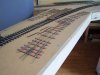
It's the entrance pointwork for the staging sidings and when complete is destined to fit here ....

bridging section.jpg

The loco is at about the place where the pointwork will be inserted, on the straight through leg of the formation; the diverging roads will feed the sidings, one set heading off to the groovy curtains hidden behind the end of the existing board, the others leading away in the direction the train is travelling to finish behind the cliffs behind the Barmouth tunnel and toll cottage scene.

The timber viaduct has also progressed, it now sports the longitudinal baulks. Trains run on the earlier version of the bridge which fortunately hadn't yet met its ultimate fate in the log burner.

morfa bridge 2.jpg

Finally whilst I had the camera upstairs I took the opportunity to snap the circulating train seen earlier on.


morfa playing trains.jpg
 

Neil

Western Thunderer
Not content with daydreaming, I've also managed to distract myself with gardening too. However all has not been lost as I've finished (apart from tiebars) the staging approach pointwork. Here's the rough but functional bit of track; no prizes for looking pretty.

staging junction 3.jpg

Here's where it'll sit on the bridge between Barmouth and Abertafol tunnels.

staging junction 1.jpg

Finally a close up of how it'll lead into the Pwllheli staging. For the purposes of the photo, I've stacked the temporary bridge sides on top of each other. I'm thinking that when the staging is complete I'll have this depth of side here to better visually separate the scenic from the hidden portions of the layout, even though it may be less convenient from an ergonomic point of view.

staging junction 2.jpg

It's obvious from the photos that more timber will have to be added for the sidings. I have a couple of pieces of mdf 5' x 8" that I cut yesterday waiting to have their ends trimmed to an appropriate angleand then fixed in place, but I won't waste pixels on pictures of wood.
 

Simon

Flying Squad
At first I thought you had been stirring your curried beans with your soldering iron, but then realised that I was probably looking at an old style tin of fluxite or similar.

Or perhaps you have discovered another "variety" of flux:D

Cascamite?

Worm powder?

Apologies for being fascinated by tins....

Simon
 

Steve Cook

Flying Squad
Looks good Neil, and an effective solution to the off-stage storage conundrum - the back scene looks fantastic in those shots too :)

As for 'wasting pixels on pictures of wood', don't worry, some us chaps are rather partial to baseboard construction :D
 

Jordan or Plymouth Mad

Mid-Western Thunderer
I realise it's possibly a trick of the camera, but I'm amazed how tight the curve looks in those pics, and how small that part of the layout looks from the "outside" view, if you see what I mean... it just shows what an excellent job of creating space the normal 'inside' view does..!! :thumbs: :bowdown:
 

Neil

Western Thunderer
All this busying myself building pointwork isn't going to be much use unless there's somewhere for it to go so this last week I've fabricated a cantilevered extension to the baseboard where I intend the staging yards to be located.

staging board.jpg

I've parked a train on the current single line to show roughly where the junction will be. Machynlleth and all points east to Shrewsbury and England (not forgetting Aberystwyth to the south west) will be represented by three sidings on the near section of board; Pwllheli will have a further three sidings on the distant arm of the baseboard. I'm quite pleased how neatly the sidings tuck away behind the scenery and how little space they take up.
 
S

Simon Dunkley

Guest
Will there be a "cutoff" between the two sets of sidings, so that you can reverse trains from one set of roads to the other, and cut down on handling, or will you be doing a bit of digital sorting between (or during) running sessions?
 

Neil

Western Thunderer
Will there be a "cutoff" between the two sets of sidings, so that you can reverse trains from one set of roads to the other, and cut down on handling, or will you be doing a bit of digital sorting between (or during) running sessions?

There won't be a cutoff between the sidings Simon. The entry pointwork is designed so that trains can either endlessly circulate or run round the layout from one set of sidings to the other without having to change any points mid way through their journey. The aim is that before I (or others) play with the layout I'll have a set of trains racked up and ready to go in the sidings. If my guestimate is correct I'll have enough siding space for a days worth of services as the dmu will be able to shuttle to and fro filling in the gaps between the loco hauled trains. However my day might actually start part way through one day and run overnight into the following one. There will be some sorting between sessions using the 0-5-0 shunter, though I suspect I'll find a way of keeping all stock on the rails and the train engine moving under its own power.
 
S

Simon Dunkley

Guest
I suspect I'll find a way of keeping all stock on the rails and the train engine moving under its own power.
Reverse out of arrival siding, pull forward on main, reverse back into departure siding...

Any more progress on Morfa?
 

Neil

Western Thunderer
.... Any more progress on Morfa?

Oooo yes. The Abertafol curve track has been fettled, stuck down and ballasted. A proper bridge deck (concrete pattern) fills the gap over the tideway.

abertafol work in progress.jpg

Trains now run far more happily here. (Note: re-gauged GUV in the consist)

morfa - abertafol parcels.jpg

The staging sidings entry pointwork is now in place, but with temporary wiring allowing trains to circulate.

morfa - abertafol staging.jpg

The remaining staging pointwork is now soldered, the tie bars have been fitted since the pics taken.

morfa staging points 2.jpg

There's still work to be done, but I'm close to the end of the dull stuff and near to the beginning of the arty farty bits that I enjoy the most.
 

Neil

Western Thunderer
The last couple of days I've been having a bit of an Apollo 13 moment putting together the point operating mechanisms for the staging sidings. Living a long way from any model shop and even further from one that does all the interesting hardware I've had to go all creative with what I could scare up out of my carefully indexed (ha!) stores. Here's what I came up with ....

staging point rodding.jpg

Leading off from the tiebar is a length of 1mm dia ns rod supported by pedestal bearings at each end. The pedestals are soldered up from brass strip (baseplate) and thick walled copper tubing opened out to 1.1 mm dia (bearing). Part way along the ns rod is a pocket to take the drive arm from the dpdt slide switch. The drive arm is more of the 1mm rod, a snug push fit in the switch knob. The pocket is a section of square brass tube with a 1mm holed drilled across its axis. I drilled close to one end then trimmed to length with a piercing saw leaving a longer section for the pocket end. With the switch and drive arm parked in the mid position, the point blades similarly set half way the drive arm was engaged into the pocket which was soldered to the rod to the tie bar. I'm obviously delighted to say that it seems to work, there being just enough give in the drive arm to compensate for the greater travel of the switch compared to the tie bar. Only another four to do .....
 

iploffy

OC Blue Brigade
Like it!!! Neil pure bodgeit and scarper engineering, can I make the smallest observation please as the bar is flexing to take up the longer throw of the switch should you not sleeve the rod where it goes under the running rails as I would hate to see it flex upwards and cause a pesky hard to find short.
 

Captain Kernow

Western Thunderer
Nice one, Mister. The play value just keeps going up and up. Won't be long before your visitors start bringing their own block instruments and bells, plus Offical Bell Code tables!... ;):p
 
Top