Holderness Drain North - Roundy - Roundy?

Dog Star

Western Thunderer
46 groats by 20 perches...
Um, only one of those units is length... shall we say seven by 6 and 1/4 fathoms? Just so Mick knows how deep are the waves to be overcome?

It is all double track on the main, there is no need to draw the back at this sketch stage.
You may be correct in that the lower edge (of the plan as shown) is the "back"... which is why I was asking Mick, earlier in this topic, what might be included for the remainder of the oval (given that the A, B and C sidings comprise less than 50% of the circuit / area - not sure if this number is approximate, those sidings have too much wood from the trees).

regards, Graham
 

SimonT

Western Thunderer
Graham,
from a PM with Mick I believe that the sidings should be loops, although this is outside of the diagrams seen so far. As to how we do this, coming in the next episode of Down The Drain .........
Simon
 

Dog Star

Western Thunderer
from a PM with Mick I believe that the sidings should be loops, although this is outside of the diagrams seen so far.
Simon (and Mick),

Your comment above is similar that which I made earlier in this topic, see this post . I think that there is little to be
gained from the East Sidings having the same "content" and "context" as the West Sidings... I do wonder how Mick is going to uncouple any timber wagons in the East Sidings unless there is a "walkway" around the outside of the layout (just what is the dimension "across" the West / Main / East in that corner?)

Unless you are referring to the fact that the yards are laid out with each pair of sidings as a loop with intermediate crossover? (thought - given that the GWR had "Barry" slips, ought the arrangement of sidings here be nicknamed as "Hull" crossings?)

The repeat of the OS map today has reminded me that the "main line" has a double junction further round... hopefully one of the Micks can explain and put forward a reason for that feature appearing at around "4 o'clock" on 7mmMick's model.

regards, Graham
 

micknich2003

Western Thunderer
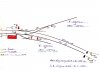
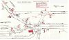
000 HOLDERNESS DRAIN NORTH 2.jpg Here's the signalling plan. Holderness Drain originated in the early years of the last century as a new junction on the Withernsea Branch to give rail access for the building of the New Joint Dock, now King George Dock. At this time the signalbox was known as "Joint Dock Jct. c1917 the Withernsea Branch was relaid to the north, and the signalbox and junction was abandond. The box was to be demolished but for some reason there was a change of plan, and the sidings as per Mick's layout were laid in. "A" Sidings, are on the formation of the abandond portion of the Withernsea Branch. 000 HOLDERNESS DRAIN NORTH 1.jpg[
 

James

Western Thunderer
Come in Mr Wells, in a previous life you were a PWay Engineer, comments please.

Before I started pulling levers for a living I was!

There's a bit of a kink there but for freight only and industrial lines (excluding some upgrades now where frieght only lines are virtually to high speed passenger standards in some cases!) providing there's no twist, then it's acceptable. Was there a change of gradient at the toe end of the junction?
 

micknich2003

Western Thunderer
Mention was made of working the traffic and complex shunts. At Mick's suggestion, I'm posting details of the lever frame and the releases etc, used in conjunction with the signal diagram, it should give a good insight into what actualy went on. I will type out and post the "Special Authorities" later. 000 HOLDERNESS DRAIN NORTH Nomanculture 3.jpg
 

7mmMick

Western Thunderer
Firstly many many thanks to Simon for working up the Templot plan and although at this stage it is a first draft it gives me exactkly what I need in as much as the rough space I will need for the project as a whole. To try and answer some of Graham's questions and what I have envisaged so far ( subject to change or total deletion) the sidings to the east, A sidings will wrap around the main up and down and follow the curve of the layout, I'm hoping to have the point at the far end to keep them as loops of two sidings but i'm not sure there will be room to build the intermediate crossings, in fact I'm not sure why they'd be used. Unless of course you could move two loaded trains out of a loop without having to shunt several trains to access on at the end ???

The line to the docks, which is seen to curve away to the right between A and B sidings climbs to cross Heddon Road and then runs down into the King George Dock. I want to try and keep this gradient and from the viewing side hopefully you will see lots of activity in A sidings whilst watching a WD slog up the bank and away into the fiddle yard ? If the gradient can't be acheivedin the space I will try and create this by the sidings dropping down to still allow a shallow climb and the insertion of Heddon Road Bridge( with road vehicles travelling to and from the docks ) and try and make this into a senic break around this area?

I intend that B and C sidings will move further in towards the main as well and again follow the curve of the layout more. C sidings are marked ' Timber Yard ' on the OS Map and I thought this end of the layout would be something more built up, maybe with a private siding with it's own industrial type loco servicing it ? I don't want things to be too crowded but I want the operational interest to be there.

One thought is to bring Holderness Drain around further to the left corner of the layout and concentrate the Dock workings and shunters moving in and out of A,B and C sidings here and then bring the Witherensea bracnh in and have this built around the right corner to cover all operational requirements. I have always struggled with thsi idea and I can't help thinking it's a bridge too far. To be honest I loved the appeal of a ' real place ' done properly and not too many things added in to make it too crowded and not believable and I worry I'm in danger of doing that. I absolutley adore Bramblewick for many many reasons and although this won't be a patch on the work of art that is Bramblewick I love the fact that Mr Harland captured Robin Hoods Bay and it's surrounding area so well, it just worked as it wasn't too busy.

Thanks for posting up the above diagrams Mick, now people can see that Holderness Drain North Box has thirty levers and you can see how they controlled movements. Talking with Mick the idea around operation will be that a lever frame, Identical to the box will be constructed and will be worked by a signalman to control all movements around the layout. That's the idea in any case. I'm looking forward to seeing the special instructions as from what I remember it allows Dock shunters to bring trains to and from the yards here without brake vans, aloows propelling trains up from the docks and I think some wrong line working ? Footplate crews communicated with the Bobby by means of a series of whistles. It would be nice to try and emulate this on the layout, although I'm not sure about all the whistling :))

Lastly the uncoupling in A sidings is a problem, I'm not a big fan of the automatic types and prefer simple three links as per the real thing. I will ponder further on this, it may be that operators will take it in turns to sit at that side and work A sidings ?

Lots of food for thought here and I would really appreciate any thoughts from anyone to steer me one way or t'other please,

ATB Mick
 

micknich2003

Western Thunderer
Here are the working instructions for Holderness Drain as put together by a late Relief signalman approx 55 years ago. The other details are from the 1960 Appendix, but are practicly the same as in 1950, the time of Mick's layout. I now look forward to spending an hour or two, designing the mechanical locking for the proposed lever frame.

004 HOLDERNESS DRAIN Special Instructions.jpg
 

micknich2003

Western Thunderer
It was a onetime common practice to have a shunt stick on the front frameing of Transefer Pilots, there where no turntables, so obviously, tender first running one way.
The signal arm ref to the train is obscured by the engine's exhaust, see attached signalling diagram, 18/20 signals top left corner.
 

Attachments

  • 00B KING GEORGE DOCK 2.jpg
    00B KING GEORGE DOCK 2.jpg
    395 KB · Views: 15

7mmMick

Western Thunderer
Here are the working instructions for Holderness Drain as put together by a late Relief signalman approx 55 years ago. The other details are from the 1960 Appendix, but are practicly the same as in 1950, the time of Mick's layout. I now look forward to spending an hour or two, designing the mechanical locking for the proposed lever frame.

View attachment 31421

Thanks again for posting mate, very interesting to read the section about the assisting engine at the rear, I had no idea trains were banked to here, should make for more interest on the operation front. Do any photos exist of assisted trains in this area ?

ATB Mick
 

micknich2003

Western Thunderer
Interesting, so why is it not a bracket signal like all the others for a junction, can't be for lack of space or sighting surely?

Originaly all the direction signals were conventional brackets, as and when they were renewed straight posts with "Stacked Arms" were employed. Top arm always reads to the most Left-hand Route. Being a Goods Only Line, there was no requirment for a conventional bracket signals, straight posts and stacked arms are far cheaper, both in first cost and later maintainance. For what it's worth, and from my notes, the dates of the alterations are set out below. All signals were new in 1914, and as can be seen had a forty year life expectancy.
As an aside, my drawing though a copy of a so called "Offical" drawing shows KGD as it never existed.

WON 38, 1953 (5th appearance) says:
King George Dock: Bracket carrying:
No. 59 Coal Sidings No. 2 to Up H & B Mineral Home;
No. 58 Coal Sidings No. 2 to Up NE Mineral Home;
No. 57 Coal Sidings No. 2 to H & B Mineral Sidings
replaced by a straight post carrying Top Arm No. 59, Bottom Arm No. 58, and No. 57 Disc positioned immediately approach side of Nos. 58/59 signal post. All 3 yards nearer signal box. Upper quadrant.
I think 57G might have read through 52W and ?W (a single slip) onto the Down side of the Down (High Level H&B Mineral, which emerges at HDS as the H&B Sidings, connected to the Down Main by 10W and 11W, and protected by 20G.

Thursday 24 June 1954.
No25 Down N E Mineral to Coal Sidings No1.
No27 Down N E Mineral to Coal Sidings No2.
No32 Down N E Mineral to Coaling Berths.
Existing bracket renewed as a straight post signal with miniature arms.
No25 Top arm.
No27 Middle arm.
No32 Bottom arm.

11/12/1955 [M. N.]
18 & 20 signals renewed as 2 arm straight post

1956.
No12 Up H B Goods Starter.
No13 Up H B Goods Starter to Quay.
Existing bracket renewed as a straight post signal with a 3ft 6ins left-hand side bracket 2 yards further out. No13 now miniature arm.

Sunday 11 December 1956.
No18 Down N E to Down N E Goods Home.
No20 Down N E to Down N E Mineral Home
Existing bracket renewed as a straight post signal.
No18 Top arm.
No20 Bottom arm.

 

James

Western Thunderer
Here are the working instructions for Holderness Drain as put together by a late Relief signalman approx 55 years ago.

View attachment 31421

Things like this are fascinating - they are perhaps more valuable than many of the items which have been preserved.


I wonder how many of the current signalmen would fare working like this?! Mick, imagine 'Super Sig' there! :D
 

micknich2003

Western Thunderer
James, HDN, was usualy a "Straight off the Street" job. By all acounts, my late father, who was then at KDG terrified them when he answered the Block Phone with "WHAT"! Then there was the tale of the Old Bloke getting out of his grave at midnight, and smoking his pipe. As for "Super Sig" forget it, he would cause that much trouble he wouldn't last five minutes.
 

micknich2003

Western Thunderer
NER Signalling Programmes 1921 019.jpgNER Signalling Programmes 1921 020.jpg
I'm not 100% sure how or why Mick chose HDN as a prototype, but he is extremly lucky with the amount of original material that survives. Attached above, the three pages of the 1921 NERly opening notice. Enough details/dimensions have also survivied to enable a decent model of the signalbox to be made.
The opening notice does not fully match the mid '50's signalman's notes, and pressumably at sometime, there must have been alterations to the interlocking etc.
 

Osgood

Western Thunderer
The pages above are intriguing - I take it the normal practice was to produce in booklet form regular track/signalling updates which would be circulated to all companies? For example this one contains detail for HDN yet also for the Lake District!
 
Top