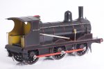
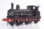
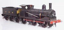
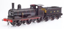
The Heybridge Railway, 1889 to 1913

GER Y14 - assembly after painting

Richard Gawler

Western Thunderer
DSC_2353.jpeg
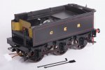
To recap slightly, this is my Y14 and its tender on 15th March this year. I bolted the subassemblies together before sending them off to Warren for painting.

I have now completed the subassemblies for the tender, so here are some photos of this activity.
DSC_2978.jpeg
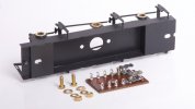
The r/c speed controller has no output protection. A dead short across the motor terminals is Unlikely but if I fit a fuse and it never blows I will have some peace of mind.

DSC_2983.jpeg
As an apprentice in the 1980s, machine screws were not only still used, but were tightened so the slots matched up.
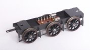
DSC_3007.jpeg
I like this palette of black and bright metal with red highlights and it is going to continue thoughout the model.
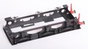
DSC_3020.jpeg
Warren asked me to leave the axleboxes and springs off the footplate assembly to make his lining task easier. I have now put them, I used epoxy glue straight on top of the paint.

I found some daylight between side frame and fooplate. I suppose, I never looked for it properly :rolleyes:. It's a bit late to get the torch out so I put a narrow bead of the epoxy along the inside of the gap. I used masking tape to keep this tidy.
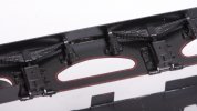
DSC_3028.jpeg
I warmed the glue with the hair dryer and this is where the glue crept through to the outside. It won't show from usual viewing angles.

DSC_2986.jpeg
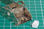
The bosses on the backs of the axleboxes fouled the hubs of the wheels so I filed them down to suit.
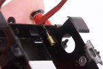

DSC_3022.jpeg
There isn't enough room for 10BA nuts on the buffer stems but there is room for some small bore tube with a flat filed onto one side. The stems are steel and the tube is brass, so I simply let the buffers cut their own threads and screwed them into place.
DSC_3030.jpeg
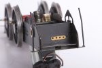
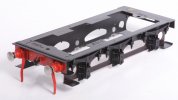
This is the completed footplate assembly. The lining on the buffer beam and buffer stocks is almost unbelievable. I have left off the coal regulator, this can go back at the very end after the wiring is done :)

I put a lot of planning into this build. Time will tell whether I did enough, but the shortened flange on the fooplate between the leading and centre axles makes a space to let me reach the programming button on the speed controller board.
DSC_3015.jpeg
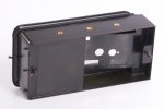
The rear handrails go into small-bore tubes soldered into the body, so it was easy to fix these into place (nail varnish) and hopefully they will stay put.
DSC_3044.jpeg
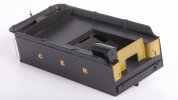
The prototypes had a visible line between the flares and the tank sides but I found it difficult to provide something right. This looks a bit rough here but it will look better when the model is moving on a layout :D

DSC_3047.jpeg
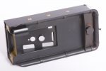
I found the equivalent joints on the top much easier, lots of 100 degree solder filed to shape.

This completes the work on the tender before adding the r/c equipment.
 

spikey faz

Western Thunderer
View attachment 187458
To recap slightly, this is my Y14 and its tender on 15th March this year. I bolted the subassemblies together before sending them off to Warren for painting.

I have now completed the subassemblies for the tender, so here are some photos of this activity.

View attachment 187449
The r/c speed controller has no output protection. A dead short across the motor terminals is Unlikely but if I fit a fuse and it never blows I will have some peace of mind.

View attachment 187450
As an apprentice in the 1980s, machine screws were not only still used, but were tightened so the slots matched up.

View attachment 187452
I like this palette of black and bright metal with red highlights and it is going to continue thoughout the model.

View attachment 187454
Warren asked me to leave the axleboxes and springs off the footplate assembly to make his lining task easier. I have now put them, I used epoxy glue straight on top of the paint.

I found some daylight between side frame and fooplate. I suppose, I never looked for it properly :rolleyes:. It's a bit late to get the torch out so I put a narrow bead of the epoxy along the inside of the gap. I used masking tape to keep this tidy.

View attachment 187456
I warmed the glue with the hair dryer and this is where the glue crept through to the outside. It won't show from usual viewing angles.

View attachment 187451
The bosses on the backs of the axleboxes fouled the hubs of the wheels so I filed them down to suit.


View attachment 187455
There isn't enough room for 10BA nuts on the buffer stems but there is room for some small bore tube with a flat filed onto one side. The stems are steel and the tube is brass, so I simply let the buffers cut their own threads and screwed them into place.
View attachment 187457
This is the completed footplate assembly. The lining on the buffer beam and buffer stocks is almost unbelievable. I have left off the coal regulator, this can go back at the very end after the wiring is done :)

I put a lot of planning into this build. Time will tell whether I did enough, but the shortened flange on the fooplate between the leading and centre axles makes a space to let me reach the programming button on the speed controller board.

View attachment 187453
The rear handrails go into small-bore tubes soldered into the body, so it was easy to fix these into place (nail varnish) and hopefully they will stay put.

View attachment 187459
The prototypes had a visible line between the flares and the tank sides but I found it difficult to provide something right. This looks a bit rough here but it will look better when the model is moving on a layout :D
View attachment 187460
I found the equivalent joints on the top much easier, lots of 100 degree solder filed to shape.

This completes the work on the tender before adding the r/c equipment.
That all looks very neat Richard. :cool:
 

Richard Gawler

Western Thunderer
Reinstallation of the Radio Control Equipment.
DSC_3052.jpeg
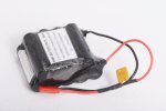
The battery pack includes a thermal fuse. Although fundamentally this protects the wiring, it also protects the model against the ills of putting a dead short across ten NiMH cells.

DSC_3058.jpeg
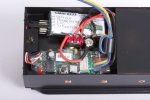
It's all a bit tight in here but if it fits inside a small GER tender it can go into many other locos. The thermal fuse is tucked away down the side of the battery pack.

DSC_3079.jpeg
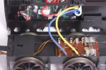
The free space between the frames is smaller than it looks because the bottom of the toggle switch goes into the space at the front. Because of this, and wanting the two brown wires to the loco to exit through the left and not the bottom, I had to discard the original connector and hard wire the controller output (blue and yellow) onto the tag board. Pity.

DSC_3068 (1).jpeg
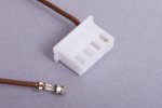
This Molex connector at the other end of the two brown wires will take the power to the loco. I find these terminals fiendish to crimp up, these are the last two out of four attempts.

The first casualty of the rebuild is the top lamp iron. I forgot it was there, put the loaded body upside down and it broke off. I do wonder how long it would survive in use. I might leave it off and be happy in the knowledge I put it on upright and in the middle during the build.
 

Richard Gawler

Western Thunderer
What recharging arrangements have you adopted, Richard?
The charger was supplied with the kit of r/c equipment and appears in my very first photo of the project. The loco has two 'modes of operation' being 'charge' and 'run', these selected by a toggle switch beside a charging socket in the coal space.

This charger is not a "smart" one (only two wires between charger and battery) so it is necessary to keep an eye on progress to avoid overcharging. The charger has a row of LEDs to show progress, some red ones and a green one. The charger needs to be switched off within 20 minutes of the green one lighting up.

This isn't as onerous as it sounds . . . I have only charged the battery three times, and only one of these occasions from empty.
 

Richard Gawler

Western Thunderer
S23 Tender, "ex-works".

DSC_3125.jpeg
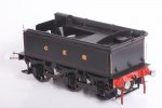
Refuelling arrangements. The black/red/bright metal palette continues if only by accident.
DSC_3123.jpeg
The axleboxes and their springs are white metal castings from Ragstone Models, I think they are a little better-defined than the ones supplied in the kit. I doubt I will ever fit the top steps at the front, I have run out of space to put them. Delivery to the railway includes fire irons but the pricker has gone AWOL.
DSC_3124.jpeg
I have put the top lamp iron back with a dab of CA, it might survive some photo shoots.

DSC_3119.jpeg
A final pic as a sort of Works Photograph.

The tender needs coupling links and coal; and maybe a tiny hole to hold a stronger lamp iron. I am calling this model finished. The loco is nearly done too, but it seems sensible to post the tender photos together like this.
 

Richard Gawler

Western Thunderer
Y14 loco chassis wiring.

The wiring for the Y14 loco is simplicity, just two connections from the tender to the motor. The idea is to be able to build a second loco using a similar tender, this tender to have conventional pickups and the same electrical connector. Then I can swap the tenders to suit the layout where the locos are running.

DSC_1130.jpeg
The very first thing I did in the loco build was to cut this slot in the rearmost frame spacer. Photographed on 15th Nov 2022.

DSC_3065.jpeg
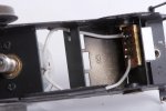
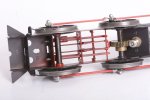
I glued a piece of stripboard behind the slot to accept the power connector.

DSC_3064.jpeg
When it fell off, I learnt I must never use CA glue on cellulose. I am glad this happened here and not with an etched plate on a side of the cab.

DSC_3106.jpeg
So I settled for epoxy glue on the edges of the stripboard.

DSC_3072.jpeg
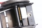
There was barely 0.2 mm of space between the rear axle and copper strips on the stripboard. This is electrically perfectly sound but a bit vulnerable to "foreign object debris" getting jammed. If I didn't have the lathe I would thin down the surface of the stripboard, but I do so I slimmed down the axle. It was a chance to try out the live centre.

DSC_3086.jpeg
The gap is now about 0.4 mm.

DSC_3128.jpeg
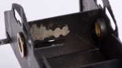
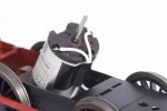
The cable tie visible in my fourth photo was hopeless, the can of the motor barely fits inside the firebox on its own. So I settled for a bit of Gorrilla tape to support the wires.

This incidentally shows how I was taught to solder wires. There are strands visible in front of the insulation and the insulation shows so evidence of heating. All strands are present and there are none loose or untrimmed. The solder is bright and shiny and the joint is easy to dismantle. This was 1981, some things I never forget even if I frequently fall short of the mark.

PS. I had to do one of the wires twice. The first one had an air gap somewhere inside it. This has happened twice to me in those 40 years, I don't expect to ring out wires before assembly but clearly it does happen.
 
Last edited:

Richard Gawler

Western Thunderer
Y14 chassis completion.

When I collected the loco, the wheels were binding ever so slightly and we reckoned this was some excess paint somewhere. After I got home I stripped the chassis. Then I realised I had completely muddled up the wheels and mislaid my notes on which shims go where.

DSC_3114.jpeg
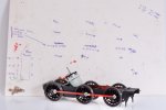
The solution is on this sheet of card, which was my work surface. Keeping the three wheels on the right unchanged and swapping wheels around on the left I found two permutations with binding, then one permutation without. Then I found a fourth permutation with binding so I returned to the third one. Then I reshimmed the wheels, also recorded here, and finally I got the motor back in. For clarity, thin = 0.07 mm, fat = 0.25 mm, but I did understand my own notes :))

Next time I might try putting blobs of coloured paint on the wheels, on the insides of the spokes near the hubs. Or tie on written card labels. Anyway, I didn’t find any excess paint and I didn’t get the tapered broach out onto the side rods.

DSC_3135.jpeg
There was a visible notch on the motion where an abrasive disc stayed too long and this notch has disappeared. I can only imagine someone put on a blob of filler or solder or something :)

DSC_3137.jpeg
I have tried to keep everything as simple as I possibly can, so ideas of thickening up the depth of the springs have been set aside. Maybe next time.

DSC_3132.jpeg
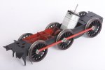
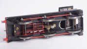
Completed chassis.

The observant (and those who have built this kit) will notice a Daft Oversight, but I have found I do not actually need to resolve it to complete the model.
 
Last edited:

Richard Gawler

Western Thunderer
Y14 completion.

I want to treat the cab interior as a separate model. With the parts for this set aside, I have now used up all of the relevant parts in the kit, all of the parts I have bought and all the parts I have made. So the model is complete as far as I want to take it for now.

DSC_3142.jpeg
The round hole below the cab floor is a drain hole I cut to make sure I dried out the model after its many baths.

DSC_3146.jpeg
I copped out on the front buffers, I was half-expecting this to happen. The only way I could see to make them sprung was to drill holes across the shanks and put pins in, and I don't have the ability to cross-drill 10BA mild steel. If I ever build the kit again I would think about setting the two gusset plates about 1 mm lower down, but it is too late to try altering things here.

DSC_3143.jpeg
I asked Warren for "the lightest possible weathering, perhaps a week out of the works" and I think it shows up well here.

DSC_3145.jpeg
Down in the noise floor, the coupling chains are steel ones from wagon couplings of unknown origin. When the blackening wears off they will still be the right colour. The whistle is the one from the kit painted in a brass colour. I have some glazing discs from @simond and I have ordered some Glue'n'Glaze to fix these on. I am expecting the cab side plates to arrive in late July.
 

Richard Gawler

Western Thunderer
GER Y14 Project for Winter 2022-2023

Back in the summer I bought myself a Connoisseur Models kit for a LNER J15; and building this up as a GER Y14 is going to be my project for the winter.

My imaginary Heybridge Railway is a short branch off the former Witham to Maldon branch and some members of the class worked the line in BR days. Going back to the 1890s, I don’t have any photographic evidence but I would like to think the Great Eastern Railway operated the locomotives on the line back then. The Y14 had a very good route availability (RA 1) so it could work across the timber viaducts near Wickham Bishops.

I doubt I will ever have room for a home layout large enough to let an 0 gauge locomotive run at any speed or over much distance but I do have access to the club test track, two and possibly three garden railways, and the layouts at another club. These are all sociable places and, well, I want to have a mid-size loco of my own to take along to haul my wagons and my friend’s trains. These friends and others have variously opted for two-rail, three-rail, stud contact, analogue and digital command control (!) . . . .and so a dead-track loco using battery power and radio control seems like a good idea for me. I can take along my loco and its own controller and it should be able to run on any 0-F or 0-MF trackwork. "Only clockwork could be easier".

(As an aside, this also means for my Heybridge Railway there is a separate controller for through workings by the GER).

View attachment 171905
I have cleared my bench and this photo is my version of an unboxing video for WT.

This lot ought to keep me out of mischief for a while?

Eight months on :drool:

DSC_3168.jpeg
I noticed some red paint on the front coupling hook in my last post and the black Sharpie is still drying :)

DSC_3172.jpeg
There is a little noise during running, I think this is from the gearbox not the wheels or motion. I didn't make any provision to connect an ammeter into the wiring and I think it is best to give the model some fresh running-in before investigating further.

The Daft Oversight: after I had fixed the electrical connector onto the chassis using epoxy glue, solder onto stripboard and more epoxy glue holding the stripboard, I noticed the connector completely obscured access to the rear screw below the loco body :))

Then I discovered, there is enough friction between this screw and the hole in the chassis to not really need a nut at all. And the coupling bar gives a safety device because it passes through the slot in the buffing plate. I don't really want to do anything more today, but a screw horizontally through the buffing plate and providing a peg below the chassis spacer would do the trick.

Credits:
Canon Precision Inc . . motor
Connoisseur Models . . kit, gears and spare parts
Fosworks and Omni . . radio control gear
Laurie Griffen . . smokebox door blank and clack valves
Lyn D Brooks . . all the research I really needed
Markits . . buffers
Nairnshire Modelling Supplies . . smokebox door dart, nickel silver wire and narrow brass strip
North Norfolk Railway . . 564
Prime-Miniatures . . M0.8 nuts
Ragstone Models . . tender axleboxes and springs
Simon D . . cab glazing
Slaters . . wheels
Warren Haywood . . paint job
WT members . . encouragement, and patience :)


DSC_3166.jpeg
Time to have a tidy-up.
 
Last edited:

Dog Star

Western Thunderer
The credit roll is a nice touch... thinking about the credits for Marvel films the last part of the film is a scene that gives an insight into the next movie. As this model can be described, at least by me, as "Marvel-ous" then surely you can finish off this instantiation by hinting at the next tale from Heybridge.

regards, Graham
 

Richard Gawler

Western Thunderer
The credit roll is a nice touch... thinking about the credits for Marvel films the last part of the film is a scene that gives an insight into the next movie. As this model can be described, at least by me, as "Marvel-ous" then surely you can finish off this instantiation by hinting at the next tale from Heybridge.

regards, Graham

Of course!

DSC_3180.jpeg
Coming next - a ballast wagon from Gloucester.
 
Baseboards for a modular fiddle yard and 'Heybridge Basin'

Richard Gawler

Western Thunderer
Coming next - a ballast wagon from Gloucester.

Well that was the plan :rolleyes:


WhatsApp Image 2023-05-19 at 15.19.32.jpg
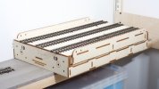
A few weeks ago I bought a second hand traverser (minus track), this already assembled from a kit by Grainge and Hodder. I was so pleased with it I ordered three new baseboard modules from the same firm to go with it.

I somehow imagined these were on a four- or six-week lead-time but they arrived last Tuesday. Knowing how modern timber goes banana-shaped within days of bringing it into the house I proceeded to ignore the wagon kit and assemble the three new baseboard modules.

One of these modules is the basis for Heybridge Basin, this will be a very simple diorama but I have started a thread for it so the posts stay together and don’t get lost between the trains here.

Screenshot 2023-05-19 19.07.36.png
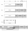
Heybridge Basin is part of a larger scheme with the traverser and the other two baseboard modules.

The intention is to build a fairly adaptable and reconfigurable fiddle yard which I can re-use later when I build a more sophisticated layout. Also, the 1200 mm module easily fits in the back of a Mk2 Yaris with the rear seat folded and plenty of passenger legroom. So if Heybridge Basin turns out to be any good, I can take it to shows.

I have done all of the "structural woodwork" for the baseboard modules so I can relax with this done and maybe I will have a go at the wagon this week.
 
Last edited:

Richard Gawler

Western Thunderer
setup.jpg
Here are three of the four modules resting on the board of my old test track. The track bed is now a little too high for comfort, but not much.

The main thing here is to show how the traverser can hold three tracks plus space for loose stock at the back. This arrangement means I use only part of the movement available, the deck doesn't collide with the display cabinet and I can always (just) reach the far corner of the layout.

I do think, the modules should be single-sided. That is to say, any module connects to any other but always with their outer sides facing the same way. Trying to get three tracks to align over four baseboards in every permutation is a bit too ambitious for me, so having the boards facing the same way greatly reduces the scope for errors. This also means, the dowels will be two males on the left and two females on the right for every module.

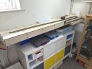
The Ikea Kallax on its steel frame (also Ikea) would make a really good base for the layout if it was a little higher. Perhaps find some longer screw-in feet or even some castors.
 

Richard Gawler

Western Thunderer
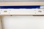
I have had a go at fitting pattern makers dowels into the first three baseboard modules. I have never found the techniques for fitting these written up anywhere so here is my approach. The important thing to remember is the clearance between a dowel and its socket is about 0.002 inch so any error in placement beyond this is going to prevent the baseboards coming together and separating properly.

DSC_3255.jpeg
1. The first module is, of course, easy.

DSC_3236.jpeg
2. Drop the dowels into these first two sockets. The dowels are rotated so their fixing holes are 120 degrees from those of the sockets.

DSC_3233.jpeg
3. Put a tiny amount of epoxy glue into the holes on the next module, for me this is my module (A).

DSC_3230.jpeg
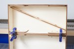
4. Place the second module on top of the first, align with M6 bolts and clamp until the glue begins to set.

DSC_3257.jpeg
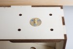
5. Separate the assembly. Mark and drill 1.5 mm pilot holes and add the screws to hold the dowels. Tighten evenly to press the dowels into their sockets.

DSC_3239.jpeg
6. Reassemble and make final checks for alignment of the baseboard surfaces.

Then repeat steps 2 to 6 for subsequent modules, for me this was just module (B) for the time being.

Adding the second pair of sockets creates a third generation and I cannot see a way around this. I used the dowels on my module (B) to set up the sockets on module (A).

DSC_3243.jpeg
7. Three dabs of epoxy glue in each recess. The new sockets have their holes at the same positions as the first sockets.

DSC_3246.jpeg
8. The assembly is made with the latest module underneath and resting on a block of wood to clear its dowels . . .

DSC_3252.jpeg
9. and then inverted to give everything a more stable base. The two M6 bolts here aren't really doing very much.

10. Again, a short wait to let the glue begin to harden and then the screws go in, just like step 5.

I have now run out of dowels but I feel I have achieved success with the first three modules.

(If the layout were to be merely sectional and not modular I would forgo the dowels and get away with M6 bolts through the holes in the ends of the baseboards).
 
Last edited:

Richard Gawler

Western Thunderer
So after all this effort I can connect board (B) onto (A) and both (A) and (B) onto the diorama.

P1050159.jpeg

P1050158.jpeg
The baseboard surfaces line up in both configurations, and from now on the locations of the tracks are set by the dowels not the sides of the baseboards.

The assembly of three modules weighs less than 3.7 kg which I think is very good for such a rigid structure.

I have ordered more dowels so I can equip the traverser module, adding this will take the all-up weight to around 6.3 kg. The track weighs 0.5 kg so if I can get through the scenics on the diorama board in 1 kg and add a bit more for the two end cheeks I ought to end up with a eight-foot layout in just over 8 kg. Which will be an easy two-man lift :)
 
Top