LSWR G6 0-6-0 tank engine

Jon Nazareth

Western Thunderer
This is a project started by some members of the G3 Society with the idea of making available a loco kit at a reasonable cost to members and would be members of the Society. If you are interested and feel like coming over to the other side drop a line to, g3projectloco@gmail.com. Michael will be able to answer all of your questions.


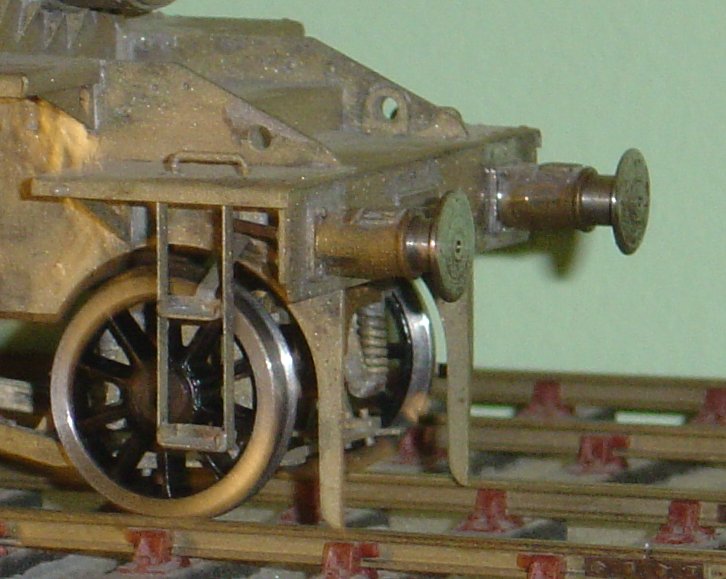
I wasn't going to start my G6 until after I had finished Jennifer Who. However, I messed up the machining of the driving wheels and had to order replacements from Mark Wood which left me with some modelling time on my hands. At the moment, I'm only skirting around the edges of the kit, cleaning up some of the pieces and progressing little jobs. In the picture are the safety chains yes, she carried safety chains. Yes, she carried safety chains when first commissioned and I'm including them on my engine. I do like safety chains. I also made up the coupling rods as you can see here. They are not fluted as supplied and it's a shame that they are not as they would have looked much nicer if they had been. The idea was to keep costs down hence the lack. Once my new wheels arrive, I shall go back to Jennifer Who but in the meantime, I'll keep nibbling away here.

Jon

IMG_5042.JPGIMG_4938.JPG
 

Jon Nazareth

Western Thunderer
Image (16).jpg

This is such a good reference drawing that I thought that it would be good to have it here.
At the moment, I'm trying to work out how the brakes work as it may be a good idea to have them working. I'm almost there but struggling with what happens with the large crank at the bottom of the brake handle. The linkage seems to dog-leg but there are so many drawn lines that it's difficult to see just what is happening. I'm sure that Ill get there after a bit more head scratching.

Jon
 

Jon Nazareth

Western Thunderer
Ah! I think that I have it. I can see the dog-leg now, it's shown dotted on the plan view but, not sure how that connects to the small end of the large crank arm. More looking later as the garden is calling now.

Jon
 

adrian

Flying Squad
Ah! I think that I have it. I can see the dog-leg now, it's shown dotted on the plan view but, not sure how that connects to the small end of the large crank arm.
As a "swag" I would guess/expect the crank is made from 2 plates formed with the dog leg so when joined they form a forked end which then fits either side of a square trunnion at the bottom of the brake handle thread.
 

Jon Nazareth

Western Thunderer
I think that I will shelve the idea of having working brakes on this G6 as the hanger/bracket/shoe print that comes with the kit won't allow this to happen. It is, all the same, a very nice component for non working brakes.

Jon
 

Mikemill

Western Thunderer
Jon

You can have working brakes as the pivot hole is at the top of the hanger as it should be, it’s just the bracket is part of the print to be a practical solution to the look of the brake assembly.


Mike
 

Jon Nazareth

Western Thunderer
I was going through the book of words this afternoon to see how the frames et al, go together and came upon a realisation. It didn't occur to me at the time, having built so many wagons but, the rear of the buffer housings will be seen when the loco is viewed from the side. With a wagon this doesn't happen as they are always hidden behind the sole bar and having a machine screw poking out of the back doesn't matter. What do other folk do about this sort of thing on locos? I was thinking of having a go at trying to turn them into self contained buffers but, the amount of work is putting me off.....Heigh ho.

Jon
 

mswjr

Western Thunderer
Most members of my model engineering club who build in gauge one, Either make self contained buffers, ( not as hard as it sounds ) or the head is a press fit in the stock and will not move, Do not really want them in the smaller scales.
 

Jon Nazareth

Western Thunderer
I looked on-line to see if if I could find a solution to the buffer problem and stumbled across one that Roxey Mouldings produce. There may be just enough material on my existing housings to put into place a variation of my own. I have a spare housing that I can practice on, watch this space.

Jon
 

NickB

Western Thunderer
Jon,

I do try to make buffers self-contained where the prototype calls for it. That is particularly so on many early prototypes where the beam is mounted on the front of the frames without any footplate to cover it. In the case of the G6 there is a footplate and some footplate angle to conceal what goes on behind the beam, so a screw poking out the back isn't a disaster for the appearance.

To conceal the attachment, I hold the buffer head with a CH screw inserted from behind the beam. The beam is drilled a clearance diameter for the head. I drill the stock through to clear the thread, and counterbore a short distance for the head itself. From the front of the stock, counterbore for the shank of the buffer head (making sure the two counterbores don't join up!). It needs a bit of working out of dimensions of the depths of the bores and the length of the screw to make sure that when the buffer is fully compressed the screw head does not project beyond the rear of the beam.

Incidentally, since you are building an Adams loco, I note that the drawings of such locos, and some photographs, show a hole in the centre of the head that gives access to the front end securing bolt so that a tube spanner or something of that sort could be used. I used that on my T3 to secure the buffers using a cheesehead screw with the head turned down and inserted through that hole - a very heat arrangement as it happened. Not all photos show such a hole. Maybe the LSWR used other types of buffer on some locos or they had a plug that could be used to fill the hole and prevent ingress of dirt when in service?

Nick
 

Jon Nazareth

Western Thunderer
Nick and Paul

Thank you for your help. I think that the slightly altered method that I'm going to try is similar to yours, Nick, and to Adrian's. I don't want to scrap what I've already done so, I'll try it out on the spare first.

Jon
 

Jon Nazareth

Western Thunderer
I machined off most of the spigot at the back leaving enough to act as a register. I then counter bored for the head of the cheese head screw to sit flush, shortened the screws and there you have it. If someone gets down and peers around the back of the beam then, the screw will be seen. But, who's going to do that? :)

Jon

Forgot the pictures.

IMG_5052.JPGIMG_5053.JPG
 
Last edited:

Jon Nazareth

Western Thunderer
Mmm, looking at the backs of those buffers and the slot in the screw.........not so sure about them now, I'll have to give that one some thought.

My question today for all of those locomotive experts out there. The frames are together and the wheels fit okay etc. and I'm going to try a first fit on the coupling rods. I need to join the two lengths of coupling rods and I'm wondering how this was done in full size practice. I've gone right through my book of Adam built LSWR lcomotives and I can't for the life of me see clearly how this was done. Did they use a very big nut or some sort of very big pin with a fixing at the back? The build manual says use a bolt peened over at the back.

Jon
 

Jon Nazareth

Western Thunderer
Eureka, I've spotted it. In the plan view of the drawing above, it shows a flat backed pin/bolt with a nut on the outside.

Jon
 

Jon Nazareth

Western Thunderer
The photo shows progress so far.
On the G3 Messaging Service, I brought up my concern over the 3mm side play on the axles. One view is that it's needed to negotiate curves, another not. Ah well, I'll just have to see how I get on.
I wanted to have a go at turning up some little oilers for the tops of the rods but I couldn't find a clear enough picture that showed me just what I was looking at. They may be too small to physically machine but, I'd like to give it a go. Or, maybe a short length of brass rod fitted to a drilled hole in the tops of the rods would give the illusion of an oiler. More to think about.

Jon

IMG_5084.JPGIMG_5084.JPG
 

Paul Tomlinson

Western Thunderer
Jon, re. the oilers... a couple of snaps taken from my copy of Locomotives illustrated, which might be of interest. The first, by H.R. Norman/Ian Allan Library is No. 257 as built. The second, by W Beckerlegge/RAS PC1614 shows a Drummond-built No. 277 with plain rods. The oilers are quite insignificant. The Adams engine also has a thin vertical pin on middle and trailing drivers.

IMG_1130.jpegIMG_1132.jpeg
 
Top