JimG
Western Thunderer
Well it's been about three weeks since I last wrote anything and that time has been taken up in designing a servo point motor which could work with micro-switches for polarity changing instead of using frog juicers. The MERG servo mounts worked well but the combination of the small throw of FS160 tiebars and the lever lengths in the MERG design meant that there was very little movement to operate the micro-switch which could have made adjustment quite difficult. Also, the pitch of the micro-switch mounting holes on the MERG design didn't match the pitch of the holes in my stock of Cherry switches.
So the 3D CAD was fired up and I started a new design of mount. It was also an opportunity for me to get my head round the developments in Solid Edge. In their 2023 edition, they had completely re-designed their user interface. I had downloaded that version but hadn't really got my head round the different new look of the software and hadn't persisted since I hadn't had a requirement to use it in anger. So I downloaded the current 2024 version and spent about a week making sense of the new look then started on the mount.
And here's the final result :-
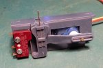
There's just over 6mm of movement on the innermost hole on the servo horn and I was looking for about 1mm movement at the tiebar, so the six to one ratio required is provided by two levers, the first horizontal one providing 3:1 and the second vertical one 2:1. There is then about 2mm movement at the lower end of the second lever to drive the micro-switch.
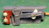
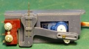
These are the extreme positions for a full 90 degree movement of the servo.
This shows the external bearing arrangements for the two arms - 9mm diameter for the second arm and 6mm diameter for the first arm. The bearing for the second arm was situated as close to the base of the mount as possible to get the 2:1 ratio with the end of the operating wire about 7mm beyond the base.
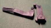
The connection between the two arms is the short stub on the first arm locating in the slot in the second arm.
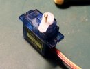
The holes in the servo arm are pretty well spot on for tapping 12BA, so the peg on the arm is a 12BA screw with a brass tube collar (1.3mm ID; 1.5mm OD) which allow it to be locked on.
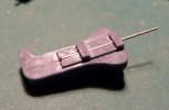
The operating wire is 0.7mm nickel silver and is held in the slot in the second arm. The end of the wire has a very short right angle bend and the wire is fitted by entering it in the slot from the left in this view and pushing it home until the bent portion springs into a hole in the arm, I'm going with the 0.7 NS wire at the moment but I've also got some 0.5mm piano wire and I might try some of that as well. That will mean just a small adjustment in the CAD drawing to narrow the slot.
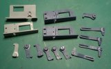
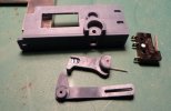
And here's some of the parts as the design developed. The light grey one in the top left corner was the first try where I was intending putting the micro-switch next to the servo. But I changed my mind and the present design started with the next light grey base, one down on the left. I then changed to another resin which meant a day of testing to get the best settings, and then all the next parts were the darker grey. Most of the adjustments made through all these parts were relatively minor - mainly fine tuning bearing and slot fits to get a good running fit with minimum play. The Solid Edge software allowed these adjustments to be made quite easily, so I tended to keep fiddling until I got things just right.
You can just see evidence of the white powder generated when the resin bearings are operated so I've applied a small amount of Labelle 106 grease to all moving surfaces and that seems to be working well on the working model. Next job now is to fit this prototype and see that it works well on the job. If it does, I'll then have to knock out another twenty. One of the design requirements for this mount was that it could be printed in good sized multiples - e.g. I can print six bases at a time on the rather small plate on my Phrozen Sonic Mini 4K printer. I haven't yet worked out the best way of packing the plate to get the best production output.
Jim.
So the 3D CAD was fired up and I started a new design of mount. It was also an opportunity for me to get my head round the developments in Solid Edge. In their 2023 edition, they had completely re-designed their user interface. I had downloaded that version but hadn't really got my head round the different new look of the software and hadn't persisted since I hadn't had a requirement to use it in anger. So I downloaded the current 2024 version and spent about a week making sense of the new look then started on the mount.
And here's the final result :-

There's just over 6mm of movement on the innermost hole on the servo horn and I was looking for about 1mm movement at the tiebar, so the six to one ratio required is provided by two levers, the first horizontal one providing 3:1 and the second vertical one 2:1. There is then about 2mm movement at the lower end of the second lever to drive the micro-switch.


These are the extreme positions for a full 90 degree movement of the servo.

This shows the external bearing arrangements for the two arms - 9mm diameter for the second arm and 6mm diameter for the first arm. The bearing for the second arm was situated as close to the base of the mount as possible to get the 2:1 ratio with the end of the operating wire about 7mm beyond the base.

The connection between the two arms is the short stub on the first arm locating in the slot in the second arm.

The holes in the servo arm are pretty well spot on for tapping 12BA, so the peg on the arm is a 12BA screw with a brass tube collar (1.3mm ID; 1.5mm OD) which allow it to be locked on.

The operating wire is 0.7mm nickel silver and is held in the slot in the second arm. The end of the wire has a very short right angle bend and the wire is fitted by entering it in the slot from the left in this view and pushing it home until the bent portion springs into a hole in the arm, I'm going with the 0.7 NS wire at the moment but I've also got some 0.5mm piano wire and I might try some of that as well. That will mean just a small adjustment in the CAD drawing to narrow the slot.

And here's some of the parts as the design developed. The light grey one in the top left corner was the first try where I was intending putting the micro-switch next to the servo. But I changed my mind and the present design started with the next light grey base, one down on the left. I then changed to another resin which meant a day of testing to get the best settings, and then all the next parts were the darker grey. Most of the adjustments made through all these parts were relatively minor - mainly fine tuning bearing and slot fits to get a good running fit with minimum play. The Solid Edge software allowed these adjustments to be made quite easily, so I tended to keep fiddling until I got things just right.

You can just see evidence of the white powder generated when the resin bearings are operated so I've applied a small amount of Labelle 106 grease to all moving surfaces and that seems to be working well on the working model. Next job now is to fit this prototype and see that it works well on the job. If it does, I'll then have to knock out another twenty.
 One of the design requirements for this mount was that it could be printed in good sized multiples - e.g. I can print six bases at a time on the rather small plate on my Phrozen Sonic Mini 4K printer. I haven't yet worked out the best way of packing the plate to get the best production output.
Jim.
Last edited:
