3mm Workbench: Scratch-building a chassis for a J50

Phil O

Western Thunderer
The wire from Cambrian comes nice and straight. I've a stock of coiled wire that I can't get straight at all...


Coiled wire can sometimes be straightened by unrolling it, fix one end in the vice, grip the other end with pliers or mole grips and give a sharp tug. Note the sometimes.
 

simond

Western Thunderer
I prefer a slow firm pull, and one can feel a little “give”, hopefully stopping before it breaks.

I suspect it won’t fly with PB as it’ll be too stiff.
 

Brian McKenzie

Western Thunderer
You won't need to do this, but an engineer friend would straighten coils of 10swg stainless steel wire, by firstly
. . . giving it a good heat up connected to his arc welder power source
. . . tying one end of the wire to a lamp post
. . . then roaring off down the road with the other end attached to the towbar of his work vehicle.
 

simond

Western Thunderer
There’s a story in a book by a Didcot fireman relating to a portly gentleman, a tricycle and a length of signal wire…

the wire was left coiled discretely, but attached at one end to the tricycle and the other to some street furniture. The portly gentleman was reported to have been quite unamused by the cycle's abrupt arrest and consequent sudden removal from below his fundament, which, along with the rest of him, had acquired some momentum by the time the end of the wire was reached.

The book might have been by Howard Glasson? I imagine the wire was quite straight.
 
Last edited:

JimG

Western Thunderer
You won't need to do this, but an engineer friend would straighten coils of 10swg stainless steel wire, by firstly
. . . giving it a good heat up connected to his arc welder power source
. . . tying one end of the wire to a lamp post
. . . then roaring off down the road with the other end attached to the towbar of his work vehicle.

Not quite the same, but I straightened 2mm scale wire rail, which was supplied as a five metre coil, by cutting it into shorter sections, then hooking up my Ganderton RSU at top setting between pliers and vice, clamping the rail in the vice and pulling hard with the pliers on the (now) red hot wire. Worked a treat. :)

Jim.
 

BetweenTheTunnels

Active Member
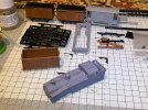
Having acquired one of the 3mm Scale, LMS Brake Van kits from Cambrian Models (which I think were originally a society product?) I spent an enjoyable 40 minutes last night starting on the build.

IMG_7388.jpeg

I am probably about as far as I can go at the moment, due to the bearings I acquired from the Society Shop having been ‘requisitioned by the authorities’ along with the various wagon kits that were purchased. Apparently they have been sent to Santa!!


IMG_7389.jpeg


Things have progressed further (but I forgot to do another photo) with the other inner end and both outer ends fitted, some led weight added and the roof fixed on.

A nice little kit to build for £11, and easy to put together - although but painting and lettering will be a job for the summer. But after Christmas Day (hopefully!) when I have got the wheels and bearings, and finished the main build, I’ll now have two 3mm wagons, which means the next job will be making and fitting the DG couplings. The plan being that these two will then become the ‘master height’ templates for everything else.

Merry Christmas to all

Richie
 

BetweenTheTunnels

Active Member
Evening all,
Done my usual trick and forgotten to update this thread again! Not a huge amount of progress in the last couple of months, but satisfyingly things have moved on a bit in the last couple of weeks!

My wagon fleet has expanded to three, nearly four wagons. In addition to the GWR Mogo van that was mentioned previously, which is now equipped with four 3mm Society white metal buffers, a 12-ton Vent Van and the Cambrian Models LMS Brake Van have been completed and wheeled. All three now await painting and transfers once the better weather gets here, but more immediately maybe next week will be the creation and fitting of DG Couplings. My next target is another Society kits in the form of a BR 21-ton hopper, the body of which is part way through construction.
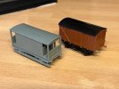
IMG_7988.jpeg

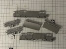
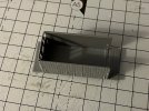
Elsewhere, I have built my J50 white metal body. This is a 3SMR white metal kit but goes together very well. The castings were, in the main, nice and sharp, with minimal cleaning up needed. The one exception was the buffers, which had quite a bit of flash on them. My plan is to remove the white metal buffers and add Society LNER loco buffers in their place. The main focus of attention is now on creating a chassis for this. 3SMR do one, but I wanted to try out a few things and also prove to myself that I can design a chassis. There are bigger Pacifics to come further down the line if this initial experiment works and I want to know ive got the skill to do it.

The plan for the J50 is my own etched Nickel Silver chassis, with 3mm Society 14.2mm gauge finescale wheels, driven through a High Level Kits Slimliner 54:1 gearbox using a HLK Coreless motor. The gearbox and motor arrived this morning, so I'll build that when I have chance and then lift the various measurements to allow the design of the chassis frames in such a way at the gearbox and motor sit in nicely.
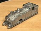
IMG_8062.JPG

The body is quiet nice and well detailed, but I think some bits may get rubbed down, such as the handrails and replaced with proper wire ones and I am not totally happy with the smokebox door and how it sits.

Sorry, these are just iPhone images and the quality isnt the best through lack of light and less than ideal photographing location! Another little project that I am on with is a 3mm display diorama, initially for photographing the stock on, but built in such away that a couple of extra boards could be added to turn it into a little layout, with return loops on each side.

Both boards will be A4 sized to go into Really Useful Boxes for storage when not in use, the track layout is nothing complicated, just a couple of sidings set on an embankment, surrounded by trees. Something to be able to test my loco on when built, to run the wagons up and down and see how they ride. Also a chance to try my hand at scenic modelling that I have not really done in many years! More on that coming up, but a sneak peak at the basic track layout and board design is below...

3mmtestbed.png

I have taken the Templot drawing for the track work and imported this into Fusion360, the CAD package I use, to be able to build the wooden frame around it, which I am then going to have CNC or laser cut. I like building things, but precise woodworking with straight cut lines is definitely not my forte!

This is in essence two boards - Board A is just the double track running through scenary, (left half) while Board B is the double track, point and three sidings. (right hald). The board design (as it currently stands, unfinished) using 9mm birch ply for the outer base of Board B is included below:
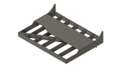
3mmtestbed v3.png

I am hoping that the design may go off to the cutters by the end of next week as there is a 3mm East Midlands Group meeting that I am hoping to get to in mid-April, and I'd like to take it a long, although its not going to be anywhere near finished!

Richie
 

BetweenTheTunnels

Active Member
Well where did March go to? Its just flying this year ... I need to find which button is the brake!

Family life has once again taken over, I have just about got the diorama boards finished in 3D planning, so I am not far off getting them cut now. My current plan is that the CNC cutter can sort out the timbers for the paintwork at the same time. It may have slightly grown to another board that includes the yard throat!

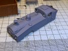
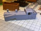
The J50 has been through the first stage of 'filler' process and had all the little gaps filled, following which it was given a light initial spray of grey undercoat and now looks very nice. No further on with the chassis, but hopefully soon that will progress. The High Level Kits gearbox and motor are here now, and I have got to have a trip to Lincoln soon, so the DCC (motor only at this stage) decoder and stay-alive will get picked at that point.

Wagon wise, I am continuing with the kits, the's now another box van and I am part way through an LNER 20-ton coal wagon (the first of five I have to build). The body was a bit of a s*d to get together with all the angles, but I have got there. Then I lost the instructions, which didnt help as I couldn't work out where all the remaining angled bits went! Now found another instruction set so can get back on with that. Also start on construction of the first DG coupling for them this afternoon.

Finally I am about 40% of the way through completing the drawings for a Mk1 SO vehicle, so I am hoping that together with the J50 chassis will go off for etching together and fill a sheet. I have followed the Comet principle of construction, but still need to give through to rolling the brass/nickle silver for the roof .... and more importantly how the roof will attach to the coach.

Some pics of the J50 to follow this evening, once I the primer has dried.

Richie
 

BetweenTheTunnels

Active Member
Oops I forgot to add in the photos last night! So the primer dried well, but showed up some of the imperfections in the white metal castings, which I had expected.

IMG_8269.jpegIMG_8271.jpegIMG_8272.jpeg

So I spent 20 minutes and went over it with some filler in various places - looked a bit like a poka dotted J50! But having given it another spray this afternoon, I am really happy with how its come out. I'll update the pictures tomorrow. The last picture was taken before a minor catastrophe when I tipped over half a bottle of Humbrol Liquid Poly! The fumes certainly lingered.......
 

BetweenTheTunnels

Active Member
Well my workbench has ground to a halt just lately, as work trips away and family life have taken over. Hoping to get back on with things slowly. I've been sat pondering the bogies for the Mk1 and Gresley coaches that I've been designing, and it brought me to a query...

What is the accepted standard for 3mm - compensated or not - when it comes to coach bogies. Hopefully each will be fitted with pick-ups feeding to a bespoke PCB strip i've designed for the lighting, which will have a capacitor (or battery) / dcc function decoder built in for lighting. Part of me says going for compensated design should lead to smoother running, but as im hand-building the trackwork anyway, another part of me says its not needed?

The bogies are an etched nickle silver design, onto which 3mm Society bogie frames will be mounted.

Anyone, any thoughts?
Richie
 

Bloomer1009

New Member
Well an hour or so working on the Gresley etches last night ended up being a total waste of time! My own fault really, getting to grips with the new soldering iron and trying to solder the door vents onto the main bodyside etch. I ended up with too much solder on, then the vents wouldnt laminate with the main etch.

I concluded that lack of heat with was the problem, despite the new iron being an Antex 50W and set to 450 degrees - I think the default bit that came with the iron is only a 2.3mm bit, and am still waiting on a 6mm bit, the largest Antex do, arriving in the post. I think that should help the issue, and suspect the brass is acting as a heat sink against the a glass craft board and the current bit isnt big enough to heat the brass sufficiently. Ah well, another part of the learning curve, and of course as is typical with me, I chose one of the harder coach types to start with!

Richie
Hi Richie,
I think that you have identified one of the problems on your own, which is the brass that you are soldering is becoming a heatsink and dropping the temperature below the solder's melting point, the bit/iron combination is being drained of heat and the element cannot keep up.. You have a heating element rated in watts and the higher the wattage the longer the iron can give out heat.
There are one or two things you could try with setup you have at the moment. Firstly cleanliness, always clean away any dark discolouration which is caused by oxidization on the surface of the bit and the heating element (HE). Disconnect the bit and HE before you start and you will not get burned. If the bit fits inside the HE then twist the bit and push it in and out which will usually be enough, blow away any dust. This type of iron has the bit secured by a screw pressing it against the opposite side of the hole it is in and you will get a line of contact to transfer heat. If the bit fits onto and around the HE then loosen, twist and pump as before, blow away the dust, clamp the two together and off you go.
With regard to bits, please never file them in case you manage to penetrate the tinned surface revealing the copper base. If you use solder with a Tin content the copper will erode and form a hole.
I have just finished soldering some Slater's brass horn guides to a Fowler 4F brass chassis using a reflow technique where you tin the two surfaces that will mate, holding them together (pressure from a wooden stirrer) and applying the heat with a Marples 100W iron. In this case the bit was shaped like a flat bladed screwdriver. No solder added to the bit just a touch to the edge of the hornguide when the solder started to shine and was obviously molten. You can see that the 100 watts was able to keep pumping sufficient heat as the thermal mass kept increasing as each horn guide was added. The molten solder is the ideal conduit to transfer heat. All I had at the club that evening was plumbers solder and flux which I applied with the wooden stirrer.
When I manage to start my own Workbench stream and have learned how to add photographs I will post some pics of the Chairmans 4F which we are bringing up to date. My 13 year old Grandson and I are scratch building a pair of O Gauge MS&LR/GCR/LNER J58 0-6-0 saddle tank locos.
Many apologies Richie for adding all the above, I really hope that it will help. My mantra for soldering is to use the biggest, hottest temp/wattage combination that you can get away with. Get in and out as quickly as possible and you cannot do that with a delicate iron. I will be purchasing a Marples 100 W iron ASAP if I can find one. I should mention that I have absolutely no experience of soldering white metal items and watch out for the flux fumes, they can be very unhealthy.
The very best of luck with your endeavours.
Dave Thorn
PS I really have no idea how you can hold or see parts in the scale you are working in, my hat is raised.
 
Last edited:

Bloomer1009

New Member
Hello Dave. Is that the Dave Thorn? I've been telling you for years to join this crew. So glad to see you here!

Brian
Hi Brian,
Yes it is me, I thought I would do a little warm up before the main event and try and assist Richie, although he has probably cracked his soldering problem by now.
Thank you for your welcome.
Dave
 
Top