A lot of time spent - particularly on the buffer beam, and a little more progress. Quite early on I drew up the rivet pattern for the wide splasher T9 (this drawing should be attached as a pdf file), and used my GW Models rivet press to create a buffer beam.
The rivets aren't at all obvious on the smokebox, but they do show on the buffer beam. These were made using the 2mm scale anvil and are still a little overscale. I find it essential to pencil in the wheel settings (to 0.1mm) for each latitude and longitude so that I can keep track of where I am and need to go next as I crisscross round a workpiece as complicated as this. The slot for the hook was cut too wide, but I'll be soldering the hook in anyway as there's a big chunk of footplate structure in the way of having it sprung. The buffer holes still need opening out and moved across slightly as they drifted when drilled.

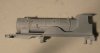
The Markit's buffers were disassembled, and the housings soldered into place together with an overscale but functional Markit's hook. This assembly was then epoxied into the rebate that I spent far too long filing out.

The housing bolts are represented by holes, and only the deranged would give that a second thought, let alone spend even more time doing anything about it! Next we moved to the arse end and made a combined cab floor and splasher side from .010" nickel silver, For best fit I found this worked best made in three parts, I then trimmed the Caley Models backhead slightly to fit the completely none negotiable space between my new splasher sides.

Also visible above are the repaired rear steps and corner. Three of the steps needed repair which was done by either slotting or rebating little rectangles of tinned nickel silver into the Wills casting and soldering up with 100° solder for strength, this was a little fraught as the melting point seemed a bit close to some, but not all castings in the kit, particularly any sort of extremity. [Edit] I faithfully put the missing rear middle step where it was before, not noticing that the middle steps at the rear were at different heights - also true of my own kit. [/Edit]


Following my friends' dad the front footsteps were fitted flush to the valance where they were very poorly located. Only then did I look at a photo of the real thing and realise that they should be inset. Once unsoldered and cleaned up for refitting, they turned out to be just poorly located in their new positions and very difficult to get square. In securing plenty of low melt solder was used - not pretty. In washing down afterwards it seems our hot water may be a little hotter than 70° (a very bad thing anyway), this became apparent when one of the front steps started to move, requiring it to be re-visited with soldering iron. One of the original front steps was deemed beyond repair and was replaced from my own kit.
That is a very long driven wheelbase, yet 1mm short of where it should be. Why that should be is a mystery to me, as I don't believe the kit was ever intended to take a proprietary chassis.